Five Port Fast Ethernet Managed Switch
2011/08/19 98 Comments
This project is the complete design of a 5 port fast Ethernet switch, based on the Micrel KSZ8995M switch IC with integrated PHY and an ATMega168 8-bit microcontroller.
The hardware was originally developed in 2009, because I needed a compact, VLAN capable switch to expand the functionality of an NSLU2, which has just a single Ethernet port and that I was using as router for my home network.
Features
- Complete VLAN support
- Auto MDIX on all ports
- Programmable port rate limiting
- Integrated MIB counters
- TTL UART interface for external access of switch configuration

Hardware
The main component of the Ethernet switch is… (surprise) the Switch! This project is based on a Micrel KSZ8995MA, which is a 5 port switch, managed, with 5 integrated auto-MDIX capable PHYs.
The device is available from major IC distributors in a 128 pin PQFP package, which can be easily hand-soldered if you have a good hand and the right tools.
If you work on electronic designs, you can also request the IC as a sample from Micrel itself… just don’t abuse the sample service!

The switch requires three power rails: 3.3V for the digital I/O, 2.5 (or 3.3V) for the analog I/O and 1.8V for the core.
As current requirements are pretty low, to keep the design simple and compact, the power supply has been designed with simple LM317 linear regulators and a series diode for the 2.5V.
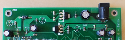
During the assembly of the PCB, the regulators have been changed to a mix of LD1117 and LD33 (as you can see from the photos), as I had these devices readily available and they fitted on the LM317 pads.
If you are redesigning the the power section, I suggest to use two LD1117 with a proper thermal pad, or a buck converter.
The switch IC has the basic configuration bits exposed as pinstrap on some 0R shortable jumper.
To use the switch in unmanaged mode just don’t short any pinstrap, to use it in SPI salve mode so that it can be configured from the microcontroller short the jumpers as in the picture.

The switch IC is managed by the small Atmel ATMega168 microcontroller using the a TTL UART port on the host side, and an SPI port on the switch side.
Please note that to interface the TTL UART port with a standard RS232 port, you need a TTL-to-232 level shifter.
The board has an AVR910 compatible 2×3 2.54mm programming header for the microcontroller.
As for the Ethernet ports, there are five connectors with integrated magnetic. You can find compatible connectors from many manufacturers, just double check the integrated LEDs polarity (I designed for Pulse but found out that Halos are different).
Software
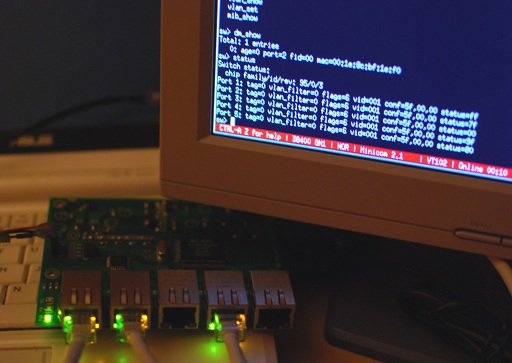
The firmware for the microcontroller implements a simple command-line interface to access the internal registers of the switch IC.
The interface can be used with a serial emulator application, like minicom, configured as 38400 bps, 8 data bit, 1 stop bit and no parity.
Available commands are:
- help: print available commands
- rd offset count: read registers
- wr offset values…: write registers
- status: print port status
- sm_show and dm_show: print internal MAC tables
- vlan_show: display current VLAN table
- vlan_set addr valid membership fid vid: set vlan entry
- mib_show offset count: show mib records
Refer to commands.c source file and switch IC documentation for further details.
Instructions to build and flash the firmware are provided in the README file in the repository.
If you need to store a specific configuration, you can hardcode that in the main function, before the “start switch” command, such as in the “start_mode_A()” function, disabled by default in the main.c file.
Files
All project files, including schematic, layout and firmware source for the microcontroller, can be found on GitHub.

The schematics in PDF version can be downloaded from here.

Happy switching!


I have one :)
You are my first (and only) beta tester!
a great project! – GM
Ciao, complimenti per il lavoro!! sono un neofita e ti vorrei rivolgere una domanda: con quale criterio hai dimensionato numero e capacità dei condensatori di filtro che si vedono nella parta bassa dello schema?
Ciao e ancora complimenti!
Ciao, grazie per i complimenti!
Se stai parlando dei condensatori di filtraggio sulle rail di alimentazione, sono arbitrariamente fissati a 100nF e sono uno per ogni pin di alimentazione. Anche nel layout in teoria vanno piazzati uno vicino a ogni pin di alimentazione, sempre che sia possibile, sulle schede a due layer a volte diventa complicato.
Lo scopo e’ compensare i “tiri” di corrente della logica digitale e la conseguente propagazione di disturbi sulle alimentazioni (si dice…), di fatto anche se non li monti tutti la scheda funziona benone lo stesso ma potresti avere problemi in condizioni particolari.
Se invece parli dei gruppi 50Ohm-50Ohm-100nF, si tratta delle reti di polarizzazione dei tasformatori ethernet, e il disegno dipende dal tipo di pilotaggio del trasformatore da parte del PHY (in questo caso dei PHY integrati nello switch), chiaramente devi riferirti ai reference design e documentazione dei relativi integrati per capire come piazzarli.
Ciao!
Si, parlavo dei condensatori sulle tre linee di alimentazione. ho visto che dedichi attenzione all’alimentazione del pin 123 (+1.8VPLL). deriva dalla tua esperienza diretta? o sono io che non riesco ad interpretare bene il data sheet del componente micrel?
Ciao, e grazie per la disponibilità
Beh, generalmente le alimentazioni dei PLL hanno quel circuito di filtraggio addizionale, non a caso il pin ha un nome diverso dagli altri alla stessa tensione. Il circuito comunque e’ preso dal reference design e il datasheet non indica necessariamente questi accorgimenti, che a volte vengono indicati in documentazione addizionale e a volte vengono lasciate a discrezione del progettista.
Ciao.
Ciao Fabio,
ne vorrei costruire uno! come connettori ho dei magjack SI-50158 con trasformatori ethernet integrati. pensi che la rete 50ohm+50ohm+100nF (sul reference design le chiamano terminazioni) possa andare bene anche per questo connettore o devo valutare qualche dato in particolare che non conosco?
Ciao e grazie per la disponibilità
La polarizzazione va benone, dato che dipende dal PHY non cambia col trasformatore.
Per i connettori invece mi pare che i MagJack che hai indicato abbiano un footprint differente (sono a contatti inferiori, tab superiore e led superiori), al contrario nel mio progetto ci sono dei Pulse serie J0026 o equivalenti, che hanno tab e led sul lato inferiore. Il footprint chiaramente e’ diverso.
Una volta beccato il footprint, il disegno dei trasformatori non dovrebbe farte molta differenza.
Occhio anche alla polarita’ dei led, come scrivo nel post ho dovuto modificare degli Halo per renderli compatibili.
Saluti!
Ciao, Fabio
sono arrivato alla definizione dei piani di massa. vorrei chiederti come mai hai splittato i piani di massa dedicandone uno ai connettori RJ45? come calcoli il valore dell’induttanza di collegamento tra i due piani? quali sono i benefici rispetto ad un solo piano di massa?
Ciao e grazie per la pazienza :-)
Ciao Paolo,
ancora una volta lo split e’ preso con fede dal reference. I miei colleghi piu’ saggi mi dicono che la separazione dei piani puo’ tornare utile per intervenire se fosse necessario filtrare rumore o altro in applicazioni strane.
Tieni conto che quel piano viene direttamente collegato agli shield di eventuali cavi shielded/foiled collegati allo switch, e in questo caso ci sono diverse possibilita’ di filtraggio per riportare lo shield a massa evitando problemi da disturbi o ground-loop, problema che comunque non si ha usando cavi UTP, ovvero la maggiorparte dei cavi usati per applicazioni Fast Ethernet.
Per un prototipo che vive su un tavolo di un ufficio quindi non ha nessuna utilita’, nei miei montaggi infatti ho usato ferriti “di recupero” o zero-ohm a seconda della disponibilita’ senza notare differenze di funzionamento apprezzabili.
Puoi comunque tenerlo e poi metterlo in corto col signal ground nei prototipi. Se noti fenomeni strani (lock/reset dello switch) usando cavi shielded o chassis metallici hai gia’ un punto di intervento… di piu’ non ti so dire purtroppo!
Ciao!
Pingback: Making Time Lapse Video with IP Cameras « fabiobaltieri
Hi Fabio.
Nice job man..! I ran into your project just because I am trying to do something similar (originally using a Broadcom BCM5352EKQMG and a PIC controller). Unfortunatelly, there is almost no information at all about this chip on internet, just a light “datasheet” (?)).
I’d like to consult the following with you: I want to combine in my PCB the switch itself and other PIC based application (mainly sensors) and want to “internally connect” this application to one of the switch ports. That way I will have 4 ports for external use and my application will be connected by default. Ok, do you see any conflict in doing this “internal connection” with an ENC2BJ60 (from microchip) face to face , I mean, without the magnetics?
My mail is [removed, less spam :-)] . You can reach me there if you want to.
Thanks,
Norberto (form Mexico City)
Hi Norberto!
Good luck with the Broadcom! They are one of the best network ICs manufacturer, but there is almost zero documentation for their stuff. That’s probably because they don’t care about minor market or hobbyist projects. That’s actually a common situation, and Micrel here is a pleasant exception… Too bad they don’t have gigabit Ethernet switches!
As for your question, what you’re trying to do is transformerless coupling between two PHYs, which is actually commonly done in backplanes and similar application. Unfortunately the generic answer is no, unless you have some specific documentation from the vendor on how this configuration can be supported, as it depends on how the transformer driver inside the PHY is designed.
I know for sure that you can do that between some Micrel devices by connecting TX/RX pairs with a specific R-C network, but as you have an ENC28J60 on the other side I would suggest you to use a single transformer anyway between the two.
Apart from that, you may want to read the application note for “Capacitive Coupling Ethernet Transceivers” from Micrel here:
Click to access an-120.pdf
and “Transformerless Ethernet Designs” from Vitesse here:
https://www.vitesse.com/products/download.php?fid=3484&number=VSC8244
Both are vendor specific documents but contains some interesting information about the problems involved.
Hope you find this stuff useful!
Fabio
You might have better luck with the Atheros AR8327-AL1A gigabit switch chip and a PIC. Parts are easy to source on Alibaba and the datasheet is findable on findable on Google and Baidu
Hi Jamie,
thanks for sharing! I wonder if you can escape from the dual-row QFN with OSHPark-grade PCB (6mils feature, 2 or 4 layers)! :-)
Or vias, depending on your tolerance
This looks like a very nice start for my needs. In a project I have to split ethernet from one to two lines. Would it be hard to change the software to use it for 3 ports instead of 5?
Regards,
Mischa
Hi Mischa,
you could just redesign it without two of the five ports, but check the Micrel website, they have plenty of 3 port switches with VLAN capability that I think would suit your needs!
Hi Mischa, did you ever did this? Was it compact? I am having the same needs!
No, I never did, project got stalled :-( This looks like a very stable solution though.
Hi Fabio,
thanks for sharing this great project!
I have an application where I need a customized 4-port 100MBit switch with passive PoE capability via the spare RJ-45 pins. For early prototypes I modified cheap switches but it takes too long for 100pcs :-) Therefore I would like to learn how many hours you roughly spent to design the board?
Kind regards,
Franz
Hi Franz! It was a long time ago but I think it took me 4 or 5 nights to do the layout of this one. I actually redesigned a v2 (which I never published) and I think it took me one full day to modify the schematics and do the layout from scratch… Hard to count the hours since I do this stuff in my spare time, but it depends on how confident you are with the CAD.
Wow, that sounds very fast. It’s long time since I used EDA software. I’m trying to learn about the requirements to outsource a small batch production of such a customized board.
If you don’t mind I would like to ask you about the missing steps to assemble 100pcs of such a custom PCB.
This is my description of the process:
1) Design schematic + PCB Layout
2) Send PCB Layout (Gerber files) to a PCB manufacturer and receive empty PCBs
3) Source components (on reels) from different suppliers
4) Send empty PCBs, Gerber files, BOM list and reels to a PCB assembler
5) Get assembled PCBs and hope that you and the factory didn’t make mistakes :-)
PS: I think I saw the v2 schematics in your Github account, right?
Many thanks,
Franz
Sounds about right, the details varies depending on how the assembly house is used to work, some of them buys the components on their own so you just need to send them the BOM. They may also ask for the coordinate file for the pick and place machine in some specific format, and you almost certainly need to add some fiducial marker on the board, but apart from that it should be a very simple board to assemble. You’re right on the rev2, the files are on github, but keep in mind that I’ve never built one! :-) It should be a nice upgrade of the first design, using a mini USB port for power and control.
I also learnt that every company has a checklist what they can and can’t process. Like:
– Via in pads
– Too small holes
– Too small parts
– How the parts are packaged (tray, tube, tape/reel)
…
Seems I’m on the right track towards my first custom board :-)
Thanks again,
Franz
That’s true but I doubt you’ll hit on any tech limitation on a design like this since all components are pretty standard and easy to handle (there is a QFN in rev2, but nothing too fancy)… Of course checking with the fab and assembly house for their limits would not hurt for sure. :-)
May I contact you on Linkedin? I don’t want to bore you with more questions but instead would like to introduce you to our crazy wireless-mesh startup :-)
Sure!
Thanks Fabio! I’ve been looking for a reference design for a small switch for an embedded project for quite a while and this looks perfect. Question: if I only need an un-managed switch (just for a couple of IP cameras), can I skip the ATMega168 by appropriate strapping (or not strapping) of some jumpers. I don’t think I’ll ever need management for this and every bit of space I can shave off is welcome.
Thanks for getting me started!
Eddie
Hi Eddie, sure thing! You just need to flip the configuration pinstrap correctly (the PS0/PS1) and the switch will start in forwarding mode with the default (unmanaged) configuration. Not sure how it comes up if you leave the pins open but you can figure it out from the datasheet.
Have fun!
Great! Looks perfect. If I get a decent design working I’ll report back.
Keep up the excellent work on this, Fabio!
Dear Fabio, I need a switch to put on buses with IP surveillance cameras. I need M12 connectors. Most such switches are super expensive. I came across this post by you and i feel it could be a wonderful fit. before i get started on the modifications, i just wanted to know- did you run it in a live applications ultimately. Any bugs and issues we may need to take care of? Any later version you may have for me to get started on instead.
Thanks! and good work. Most helpful.
Best
Pawandeep.
Hey Pawandeep, I’m using one of these at home almost continuously since I made it in 2011 and it never let me down… I’ve actually learned about that switch IC (the KSZ8995MA) from its use in an automotive application, and I’m not aware of any problem with it from the field. Make sure to get the -I variant for the industrial temperature range (-40 to +85 C)… AFAIK this used to be one of the few industrial switch ICs commonly available from major supply chains (DigiKey: http://www.digikey.com/product-detail/en/KSZ8995MAI/576-2126-ND/1027614).
Cheers!
Oh, about the second version question: I’ve redone the layout from scratch some year ago but I’ve never built the new version… If I were to deploy these in a non DIY project I would completely redesign it from scratch anyway, with a proper DC/DC supply in place of the LDOs (at least for the first stage) and a 4 layer PCB using proper high speed design practices – my dual layer design is ok for DIY and proven to be surprisingly reliable, but I’m sure EMC and signal integrity are sub-optimal.
Emc would not be a concern if it is being packed in a metallic enclosure. Nevertheless, if you can agree on being a guide we can jointly take up the development of a multilayer board for a good managed switch. I can contribute with better regulators, pcb designing (validation by you) and prototyping. I would not be too good with firmware though.
Hey, thanks for asking but I’m not really into putting more effort in this project. Feel free to post a link to the project though if you end up sharing it! For the firmware part, if you just need the switch in unmanaged mode you don’t need the micro at all.
Thanks fabio. That was helpful. I get the gist of how to build it.
Hi Fabio,
Thanks for sharing your design, it was very helpful.
But i have problem. The Micrel KSZ8995M throughput don’t exceed 3.3Mb/s :( Do you have any idea why? Or had a similar problem?
Cheers,
Tom
Hey Tom,
never had any performance problem with the switch (I built three of these), it was always able to saturate the 100Mbps link. Are you running in default unmanaged mode? (I think there are some ratelimit register)
Hi Fabio,
Thanks for quick reply, sorry I couldn’t do that too (i was little busy ;)
Turns out it was connected devices problem, not switch itself.
Again, thanks for sharing your design.
Keep up the good work,
Tom
Thank you for sharing your knowledge about this project. I am interested in building one for an embedded design I am doing. I need an unmanaged switch. If I am going use the device as an unmanaged switch can I eliminate the CPU and associated circuitry and will the switch run on its own after power up?
Hey Arun, yeah totally, just double check on the datasheet for the various pinstrap but this runs happily in unmanaged mode without any micro or EEPROM.
Hello Fabio,
I need to do the same thing as Arun. I have already built the circuit but can’t seem to get it to work. Would you be able to look at my schematic and see if there are any major issues? Please let me know.
Btw, thanks for putting this tutorial together.
Here’s my email: –cut–
-Elmer
Hey Elmer, glad you found it useful! :-)
You could start by doing some initial check before even looking at the schematics:
– are all power supplies up to specs?
– is the crystal oscillating?
– do you get the initialization blinks on the switch when you apply power? (that would indicate that the internal logic is working somehow)
If the three above you should be at a good point already…
Fabio,
Thanks for getting back to me.
I found an error in the power supply circuit so I’m bypassing them and giving the chip the three power rails (3.3, 2.5 and 1.8) it needs from a power supply. The crystal is oscillating, I hooked it up to an oscilloscope and saw the 25 MHz sine wave. Unfortunately, I didn’t put any LEDs for the switch. Maybe I can connect them to multimeter check the output voltage. What kind voltages should I expect at the LED outputs?
-Elmer
The LED pins are open drain, so if you did not install any LED, unless you put a pullup you are not going to see anything. I think it’s worth giving it a try and hack a pullup to one of the LED pins and check with the scope. All LEDs blinks when you reset the chip and then they stay in high impedence until the corresponding Ethernet port finished negotiation. After that one of the LED pulls down for link-up and blinks on activity, and the other pulls down on 100MBps link (by default).
About the pinstrapping, I remember that on my design leaving the solder bridges open was enough to put the switch in standalone mode. Did you drive the PS0/1 and SCONF0/1 pins in any way?
Oh you could also check if the switch is trying to read the configuration EEPROM at bootup, look for activity on the SCL/SDA pins.
Hi Fabio,
This is the first time I’m going to be working with any type of networking chips and I only do it as a hobby.
When using the KSZ8995M in switch mode, none of the jumpers are shorted, so that then means it is not set to SPI slave mode from my understanding.
Does that then mean that the ATMega chip can be ommited if it is only going to be used in switch mode?
Thank you
Yeah that is correct! In that mode it looks up for an I2C EEPROM and if that’s not present it just works with default settings as an unmanaged switch.
Hi Fabio,
Thanks for sharing your great work.
May I ask why is it that the center tap connections are connected to 2.5V instead of 3.3V. I have built a similar board, I found out that connecting the center taps to 2.5V works but not to 3.3V.
Regards,
Huan
Hi! I don’t really remember the details and can’t find the electrical datasheet now that everything is under Microchip, but from what I remember some of the analog rails of the chip could work at either 2.5V or 3.3V (and it looks like in the current revisions it’s 3.3V only). I suspect that the center tap just has to be a the same level as VDDAT, so maybe you mixed 2.5V on the chip and 3.3V on the tap. Either way… I probably just copied the reference design. :-)
Another cool thing: The chip that is the successor to the 8995 has this web page:
http://www.microchip.com/wwwproducts/en/KSZ8895
and if you go down to the Design Guides section and download the guide:
KSZ8895MQX_RQX_DP_V1.3.zip
In the resulting folder you’ll find:
App Note-Migration from 8995 to 8895.pdf
which shows that a lot of passive components needed for the 8995 design (caps and whatever on the ethernet tx/rx wires) have been incorporated into the 8895 chip so it’s even easier to use! Hooray!
Oh that’s pretty cool, it should also saves quite some power when the port is not used, on-chip termination is a pretty common feature on modern transceivers as well, cool to see it here. Should update this design. :-)
Hi Fabio, While I at first cringed to see Micrel go under the Microchip name, it looks like they are actually setting up better documentation and resources such as free samples(!!!). It looks not only better, but maybe MUCH better for us users/experimenters.
Info / Feature Matrix and data sheets for their Ethernet Switch chips are here:
http://www.microchip.com/ParamChartSearch/chart.aspx?branchID=1633
Extensive Applicatiion Notes, Design Guides, etc for the KSZ8895 (the still-in-production pretty much equivalent of the 8995 which they say is retiring) can be found here:
http://www.microchip.com/wwwproducts/en/KSZ8895
Their extensive documentation as well as new reference designs and such is a hopeful sign.
THANKS AGAIN for your terrific work on this. I hope it is gratifying for you that so many people are still using this as their first path to making their own switches. You can probably now just point newbies like me and Huan Hoang to the Microchip docs, but thanks for taking a machete and hacking out the trail for us to follow!
Happy Trails!
Yeah I was just used to the old website. :-) Also I’m happy to see some gigabit p/n in the switch category (KSZ87**), that may be an interesting followup design!
Hi Fabio,i wanna use this switch in layer 2 controlled mode with an ARM CPU which has an Ethernet MAC. How should it be connected to the KS8995MA? I mean the MII interface of MAC of CPU shoul be connected to P5 interface of KS8995MA or SW interface?
Thanks.
Hi! Yeah that should work just fine, I think that’s the main purpose of this switch, and I’ve seen it used in this mode in some commercial router already. There’s even a Linux kernel driver to control the switch via MDIO in that mode.
Hi. Good work, cool :)
I also want to use KSZ8995 (or KSZ8895) with connectors L830-1J1T-47.
Will they work correctly?
And, like any serial interface, signal RX of the connector I connect to TX integrated circuit?
P.S. I apologize for the stupid questions, with Ethernet I work for the first time :)
Hi! The datasheet mention some guideline on selecting the magnetics, look for “Selection of Isolation Transformer”. They don’t seem to refer to the magnetic topology explicit, but all the sample part number are auto MDIX compatible and have symmetric topology for the TX and RX side (makes sense…), with the 1:1 transformer in front of the common mode choke. Look for a Bel Fuse S558-5999-U7 for an example. I suspect that your p/n would work anyway but I would look for an alternative with a configuration similar to the one recommended by Micrel.
TX/RX in serial interfaces is an endless source of pain and confusion, no questions about this can be considered stupid. :-) So the Ethernet story for TX/RX I think is that you should put the TX pair on pin 2 and 6 of the connector on a switch, and to pin 1 and 2 on a NIC. In practice this device has auto-MDIX, as well as pretty much all Ethernet PHYs built in the last decade or so — which means that as long as you match the polarity of the pair you can swap TX and RX as much as you want. A nice practice in this case would be to connect the TX/RX pairs to the connector so that you get the best possible layout on the circuit board… if you are not doing the layout yourself, this would make you the best friend of your layout engineer. :-)
There is no application diagram or circuit in the datasheets. For a beginner, how should I start to design this from scratch other than to study the whole datasheet?
Hi! On application chips like this there is usually no application diagram, and the manufacturer provides a full reference design instead.
Look for the documentation under “Design Guides” here:
http://www.microchip.com/wwwproducts/en/KSZ8995
The design is pretty much a full working switch, with all possible configuration of the device (copper, fiber…).
That’s a good starting point, though you should still go through the datasheet… at least the parts about electric operations (decoupling, transformer, pinstrap, power supply, configuration EEPROM etc…).
Hi Fabio.
Very nice work. Circuit is working rev2 ? Did you test it?
I want to use one :) . Which recommend be rev1 or rev2?
I can do the soldering QFP, QFN.
Thank you..
Thanks Hasan! Sadly, I never built the rev2. This is a fairly old design of mine and there are plenty of things I would change. Unfortunately the only prototype I still have (rev1, I built three in total and gave two away) keeps working pretty much flawlessly since 2011, giving me very few motivation to build a rev2. :-)
Anyway, if I was you I would take the rev2, stick a micro-usb port for power supply and swap the two linear converters for DC/DC if you are confident with designing power supplies. Then trash the layout and redo it from scratch to put it something funny. :-) The rev2 should fit in some Hammond box… may be a starting point but it was a bit crammed in what I recall.
BTW the chip is now obsolete, you may want to check what Microchip (aw… miss you Micrel) has to offer as a replacement… I think they have some 9-port or mixed speed version with gigabit uplink or something.
Post pictures!
Thanks for the answer :)
I want make rev1, for a guarantee. I’m redrawing, to make affordable price production. (pcbway 10x10cm, 5$). I do not know Eagle :( . I am drawing in the Proteus. When analyzing the datasheets, I noticed something. J0026, J0026D01NL
https://www.digikey.com/product-detail/en/pulse-electronics-network/J0026D01NL/553-1487-ND/1036881
Click to access J403.pdf
Look here, J0026 datasheet, Page5. and your schematic. Pin connections are different. I am confused. Do you used something different ? HR911105A. Do you mind if I use it? Else, should I buy the digikey link (J0026)?
Alternative, HFJ11 (HFJ11-2450E-L12RL) ?
https://www.mouser.com.tr/ProductDetail/HALO-Electronics/HFJ11-2450E-L12RL/?qs=8uu3sA0mUduNJw%2ftWFBLbA==
Click to access fastjack-100baset-520317.pdf
Click to access HR911105A.pdf
Hanrun HR911105A, The price is affordable(1-2$ etc.)
I built all my prototypes with magjacks recovered from scrap boards… I’m not even sure what the part number was but I used at least three different models. The datasheet should have a paragraph of magnetics selection but as long as you match the plus-minus-centertap connection they should all work.
And,
https://www.digikey.com/product-detail/en/microchip-technology/KSZ8995MA/576-1039-ND/771509
Datasheet KS8995MA, Page 14;
9-VDDAT -P-3.3V-analog VDD. (2.5V or 3.3V is for B3 and previous chip revision). 3.3V is
recommended for new design.
VDDAT 2.5VDC, your schematic.
3.3VDC or 2.5VDC. Which should be?
Go for 3.3V… one less power rail to deal with!
Hello! My name is Andrew I am a part of a college robotics team at University of California, Santa Cruz.
We’re working on building an underwater robot for a competition and was in need of a network switch. The robot is going to have multiple PCBs within it that needs network connections and a pre-made switch won’t work.
You schematic seems very helpful and we were thinking of basing it off of yours but we had a few questions.
1) Do you have a parts list for all that was used for this schematic? We’re having some issue discerning everything from the schematic.
2) I’ve seen discussion between other people here about updating the switch for the modern Ethernet micro controller, and was wondering if you had any tips on what needed to be changed for the modern part.
Of course, if we do use it, we could have your name on the board or listed as a sponsor on the team website, https://www.slugbotics.com if you would like.
Thank you for your time!
Andrew (Slugbotics Electronics Team)
Hi Andrew, I saw this switch used for embedded transformerless applications (multiple SoC on the same board), it’s one of the intended application, there should be some application note or section in the manual, and it sounds like what you need. My design is pretty old at this point and I also think that the p/n is obsolete. I would recommend you pick a more modern chip (from Microchip since they acquired Micrel), and based on one of official reference design (they should come with complete BoMs and schematics.
Hi Fabio
I did it. I forgot to tell you. We have been using it for a long time. Thank you for that.
Do you suggest a more up-to-date chip? Actually, I want to sfp-fber and 7-8 port.
In the meantime, I’m dealing with underwater projects. @Andrew Gavgavian If there’s anything I can help.
Yeah there are some interesting parts on the site… KSZ8999 is 9 port with 8 100FX capable phy (not really new) and all of the new 7 port 5 phy gigabit ones (KSZ9897, KSZ9567, KSZ9477) seems to support 1000Base-LX and -SX (http://ww1.microchip.com/downloads/en/AppNotes/AN2647-Interfacing-SGMII-Port-on-KSZ9xx7S-KSZ8567S.pdf).
That’s good stuff, these are not reasonably priced and stocked on Digikey… Tempted to build one myself. Back when I did this project, the only option I could find to do gigabit fiber with off the shelf parts was some ridiculous Vitesse rectangular BGA to do RGMII to SerDes conversion. Funny that it seems like Microchip owns Vitesse as well now, through the Microsemi acquisition. These guys are buying everyone.
Is this for the tether connection to the ROV? Guess you have multiple internal subsystems in the local network segment and one or two fiber uplinks… can you share the general system architecture? Sounds interesting.
Here’s a link for the system architecture.( https://imgur.com/a/qMhakqg)
The tether is one important aspect of it for the network switch, but this is also for the inter connection between the multiple PCBs on the Robot. Competition wise, what we’re doing is MATE (https://www.marinetech.org/explorer_2019/) and the specific Explorer class. This website should have links to the specs and requirements of what we will do.
Yeah, I looked at these. LQFP, practicable. If I can find time, I’m gonna do one of these. I have looked at other products or manufacturer, not applicable because BGA :(
Yes, microchip earned a lot of money from the PIC MCU. It’s buying everyone, mercilessly.
Yeah, that’s interesting :)
Delay in image transmission is very important. This is the most challenging work.
Other problems solved. (You have a share).
Architecture:
-Main power system (just about 400VDC high power and energy transmission)
-Power distribution system (power to internal electronics)
-Power monitoring system (isolated: motor current, main current, main voltage, 400VDC etc)
-Motor driver (generally bldc)
-Main controller system (all control with STM32. RMII 100mbps ethernet. very talented)
-Comminication (switch,fiber, PLC, vdsl etc)
-Camera system (trouble :( SDI, IP etc)
-Lighting system (10000-100000 lumen)
-Sonar system (i can’t do it :D getting )
-IMU system(have developed a beautiful product, +-2 degree pressure etc)
Example:
-Main controller system
https://drive.google.com/file/d/1Ayb7wJ1oBPqW2zMCzhxaIy0bKYVmvMbu/view
https://drive.google.com/file/d/19Lgcv5qvmaFtfaWgPVQhJpVotvjjQL_6/view
-Lighting system(25000 lumen)
https://drive.google.com/open?id=10kz7YEZPozzkJxhszaqJiKVh57GU7SVX
https://drive.google.com/file/d/1HhCAo8FmL0EMGEcJS8AYbDhHM53vJn5O/view
If I need to add. Ethernet is very important for ROV system. Everything is solve with a single connection (one fiber, one twisted pair cable)
And Modbus TCP/IP with STM32 :) best friends :)
Oh wow! A bit of everything going on that system, must have been quite some work to design an integrate, so many different problems… from power to comms. Good job!
These days I’m playing a fair amount with LED lights for outdoor sport use (trail running/mountain biking)… 100000 lumes?!? That’s a “portable” sun. :-)
Micrel products are pretty much the only stuff I’ve ever found for low volume Ethernet switching projects and reasonable packages… hope it’ll stay that way. I think most high volume applications are based on Broadcom and Marvell parts, but those are inaccessible unless you have a good contact with the vendor.
Cameras on embedded systems have been a constant source of problems in my experience as well, poor/buggy drivers and poor documentation on both SoC and sensors… maybe I’ve just been unlucky but it seems like most scientific applications can’t be bothered and just use crazy expensive modules with all sort of FPGA/DSPs on board.
STM32 and TCP seems like a good combination… Only did one project with that (STM32F107 with ChibiOS + LwIP) and it was surprisingly smooth to get the network part working… good stuff!
Hey, thanks for sharing! Good job! :-)
Hi Hasan,
could you share your “Power monitoring system” for the 400V?
Any progress with the Ethernet switch?
Thanks, Jarno
400V monitoring system. I made a special card. Stm32 and special isolated voltage sensor (LEM) etc. The sensor is quite talented.
I will do KSZ9897 or KSZ9477. Too busy. Not yet.
Hasan, can we talk over email? relaxibus@akfree.it
Your welcome :)
Send me a message if you need a STM32 lwIP with modbus TCP/IP library. It can talk to everyone (computer, other MCUs, Siemens S71200, Schneider TM241 etc)
Hi Hasan,
Very interesting project :)
I’m trying to use ethernet with the STM32F107 + freertos and lwip.
I’m using a LAN8742A PHY and then i’m using a KSZ8895 as a standalone switch.
I’m using Modbus TCP and i have 2 RS232/485 ethernet gateway
It’s working but not flawlessly.
Sometimes my stm32 does not repond, and i don’t know why (modbus timeout) even if I don’t use the serial gateway
I want to get rid off the LAN8742 (I have problem to solder properly the LAN8742) and I want to use directly the KSZ with the stm32 RMII, maybe that’s what you did (can you share the design ?)
And I did my own modbus tcp, and i’m shure it’s pretty dirty, so can you share the STM32 lwIP with modbus TCP/IP library ?
Than you
Hi Bobnono,
Yes works, RMII stm32 with KSZ RMII, should work. LAN8742A good phy, Pads wide draw. Use plenty of flux and solder paste. Not use SWDIO, SWCLK etc pins while the program is running. Sometimes I realized it was a problem. I would recommend DP83848(LQFP) .
You can look at simlymodbus.ca for modbus. That’s what I did. I am using STM32 HAL firmware for TCP/IP serwer – LwIP. Thats work.
Freertos + TCP/IP (nightmare) (:
Hello Fabio
I am completely new to this, I am looking to build a 5 port unmanned switch, I notice from reading the above posts that I can just leave the ATMega out? I also am new to the software side of things, is this easy to pick up?
Yeah totally, leave the micro out and make sure to configure the pinstrap so that it starts automatically, it would run as an unmanaged switch just fine. You can also put an I2C EEPROM and set-up more complicated things (VLAN…) without a micro if you need so, just read the device manual, everything is covered there.
Many thanks, can you say what RJ45 you used? or what one you would recommend?
Good question, no idea, some random connector with integrated magnets salvaged from other prototypes I had laying around, you can even see in the picture that they are of two different types. :-) The datasheet should have some reference, as long as the footprint and transformer layout matches they should all work anyway.
Thanks – if I wanted to add PoE, then is there a way of using separate magnetic from the RJ45? as if would appear that the pins 4 and 5 plus 7 and 8 are linked through to the internal circuitry
Yeah for PoE you can either use external magnetics or a jack with embedded magnetics with the center tap broken down, both for the 1-2/3-6 and the 4-5/7-8 pair. You can find the layout on port and PoE controller datasheets, check these two for example:
Click to access 7499211122A.pdf
Click to access tps2375.pdf
For proper 802.3af compliant PoE there’s quite a bit of stuff you need in addition to the port and rectifiers, but if you just want to do a more “homebrew” non isolated injector integrated on the board, the port and rectifiers sould be enough. I think you can even find connectors with both transformers and diodes integrated.
Thanks v helpful, I am looking into the spec for 802.3af, if you have any pointers that would be great. I since have found https://www.in2connect.uk.com/wp-content/uploads/2017/04/EDAC-Magjax.pdf looking at the 13 Type jack
Hi to all! I saw this is a very old threat but still on going, awesome?
I also are looking for a small embedded switch without RJ45 connectors. It is for drone and unmanned vehicle use with IP datalink.
Is there an interest to start a joint open source project based on Fabios original work? I think a lot of people would be happy to see a project like this :-)
Thanks, Jarno
Wow, such recognition… it’s really just the reference design with an micro to initialize the switch. :-)
Fabio, you’re right. However it works for people with programming and electronic design skills ;-)
Fabio, sorry for going off topic but I was curious since you seem to focus a bit on networking…
I am thinking about a way to create what amounts to a gigabit ethernet matrix switcher to enable HDMI over ethernet in a building with three separate meeting spaces. I need to – in this specific application – take one of a number of designated “input” ports and output the identical signal on up to three designated “output” ports. In some ways, it is most like a hub, but with the requirement that the output ports can be specified. In some ways it needs to function as a patch panel, such that there’s no store and retransmit, but just, as much as possible, a straight pass through, again with the multiple outputs. The goal would be to have a microcontroller like an Arduino specify which inputs go to which outputs.
I was thinking of transistors to switch ports on and off, but the traffic may need to be bidirectional (not sure of the necessity of bidirectionality with the HDMI extenders), and the signal levels need to be maintained from input to output since gigabit uses five different signal levels. It’s been years since I even dabbled in anything like this and there’s really not a lot of specific information that I can find on how switch controllers selectively route to one port or another – not meaning the lookup tables of MAC addresses, but the physical routing from one port to another, exluding the rest. Similarly, there’s not a lot of information on how hubs would amplify or replicate the signal from one port to all others.
If it’s not something up your alley, no problem. Just figured I’d ask. Thanks for showcasing the projects. It’s always fun to see what one can make with otherwise simple components.
Hey Roy, definitely can’t use an Ethernet switch chip for that, but you can probably build something that does what you need with a series of LVDS switches. They are essentially analog switches for high speed differential signal stuff, and you can build your matrix with a mix of switches, multiplexer and redrivers. TI makes some stuff (http://www.ti.com/interface/lvds-m-lvds-pecl/buffers-drivers-receivers-cross-points/overview.html) and I vaguely remember using some Pericom device (https://www.diodes.com/products/connectivity-and-timing/interface/lvds/)… I think they would work for HDMI switching. The problem though is that you also need to handle the DDC data on the downstream ports, that may need a bit of work to replicate the input device configuration.
Can you have multiple of these switches on same network? As I understand Switch has it’s own MAC address. Does KSZ8895MQXCA comes with unique factory assigned MAC address?
I don’t think it needs any MAC address. You’d need one for STP but it’s on the host to implement it, the standard config does not do anything special and you can use multiple of these on the same network just fine.
Hey Fabio, great work. I have an urgent requirement of a custom configuration using a combo of 2 KSZ8999. My requirement is 6 x SFP + 4 x RJ45. So I will need to use 2 of these IC’s I think. Internally connecting one port each. Do I have to load any code in unmanaged mode also? Will the SFP ports work out of box or need firmware customization ?
Hi! Never worked with the KSZ8999 but it looks like ports enter fiber mode when FXSDx > 0.6V, so it seems like you don’t need any custom configuration for that (look for “100BASE-FX signal detection” on the datasheet). I would put the footprint for a config EEPROM anyway, just in case.
To use two back to back I think you could use the MII interface and configure one in MAC mode (so that you would have 8+8 ports available), but that would require a config EEPROM. Since you only need 10 ports you may just use two PHY in the capacitive coupling setup (http://ww1.microchip.com/downloads/en/AppNotes/Capacitive%20Coupling%20Ethernet%20Transceivers%20without%20Using%20Transformers.pdf).