Inside a Hantek DSO-2090 USB Oscilloscope
2013/07/10 118 Comments
As part of my electronics test gears, I’ve recently got myself a cheap USB oscilloscope: a Hantek DSO-2090.
The DSO-2090 is marketed as an 100 MSPS with 60 MHz analog bandwidth, though the full sample rate is available only when using a single channel. As Hantek also sells similar models with higher performances, I immediately took the device apart to better understand how it works and to see if it can be pushed a bit more, especially regarding the realtime sample rate.
This post is a basic analysis of how this oscilloscope works with some consideration of its limits, and it may be interesting to better understand how a basic DSO works.
PCB and Block Diagram
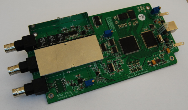
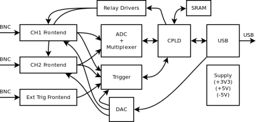
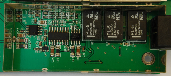
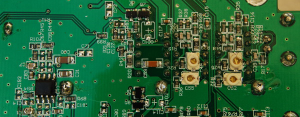
The scope is realized with a standard 1.6mm 2 layer PCB, without using any fancy BGA or QFN components. This is basically a single shot dual channel DAQ, with an analog frontend, triggering circuit, ADC, some SRAM for fast temporary storage, a Cypress USB interface, and a CPLD to control the whole thing.
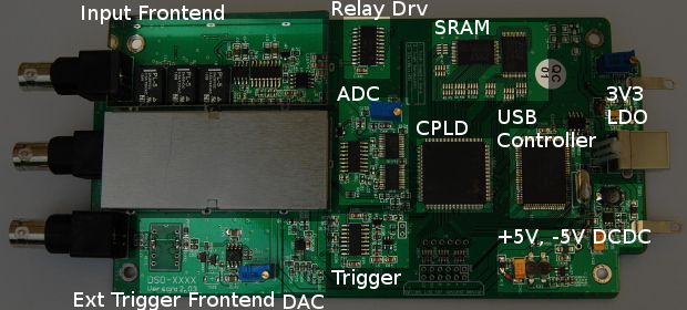
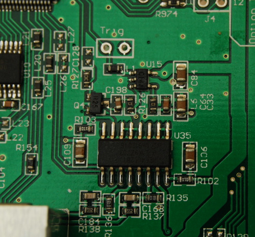
This is a picture of the PCB with the main elements highlighted (the shielding cover of channel 1 frontend has been removed):
Power Supply
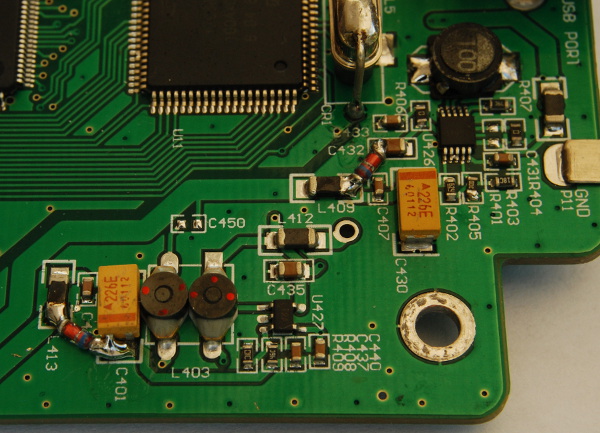
The whole device operates from USB, so the PCB has a 3.3V fixed LDO (actually two in parallel… weird!) for digital devices and two DC/DC converters (U426 and U427) to get a stable dual +5V/-5V supply for the analog stuff.
USB Interface
The USB interface is implemented using a Cypress CY7C68013A, an 8051 based USB controller commonly used to interface FPGA and CPLD based DAQ to an host via USB. This kind of host interface is really common in these devices.
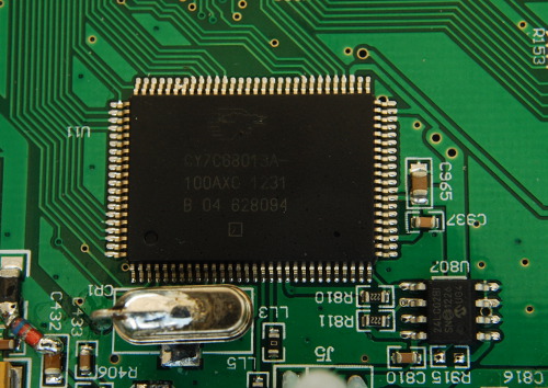
The Cypress also has a configuration EEPROM (U807) to allow device identification, but the actual firmware is loaded at runtime from the host.
Control CPLD and SRAM
The main component of the DSO is a Xilinx XC95288XL CPLD, in the 10ns speed variant and commercial temperature range. The CPLD is coupled with a pair of ISSI IS61LV256AL SRAM for realtime sample storage.
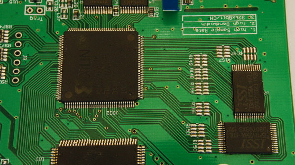
The CPLD is also attached to the ADC and other controllable components. The operating principle is quite simple in theory: the scope continuously records data from the ADC into the SRAM in a circular buffer, and stops for transferring the samples to the host when the trigger circuit shoots, keeping the acquisition delay into account. The CPLD is also used, basically as a port expander, to control other digital parts of the device, such as the analog switches.
It seems like the CPLD operates completely asynchronously from the USB bridge, and the whole thing can be easily overclocked by replacing the main 50MHz oscillator. I actually have my DSO-2090 running with a 125MHz (!) oscillator, and apart from some acquisition glitch at intermediate time/div settings it works just fine!
ADC
The two ADCs originally had their part number optimistically covered with a marker, but are actually a pair of TI ADC08060, which I replaced with two ADC08100. I did not see any improvement tough, so I think this mod is a waste of money, but at least confirms the part number.
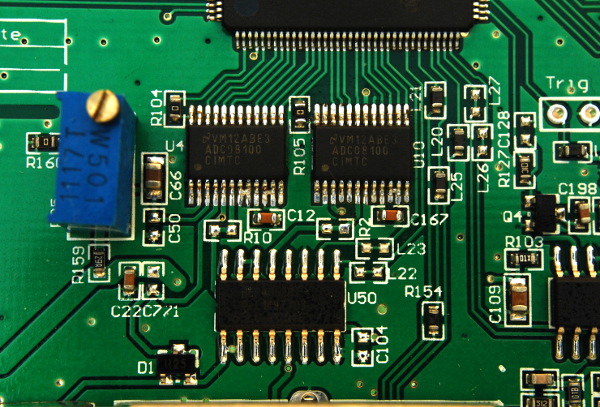
The two ADCs are connected behind a HEF4052 (U50) analog multiplexer that is used to connect any ADC to any of the two channels. This is actually useful to operate the ADCs in interleaved mode on the same channel, and obtain a maximum sample rate of 2*CLK (100MSPS with the stock oscillator).
The analog multiplexer is controlled by the CPLD, and there seems to be a couple of clamping diodes (D1, the other is bottom mounted) into both signal paths from the frontend to the multiplexer. Also, a multi-turn trimpot is used to manually calibrate the ADC full scale voltage.
DAC
This little TSOP10 device (U20) seems to be a 4 channels SPI DAC, the actual part number is masked out. This is controlled by the Cypress USB interface and has two channels wired into a buffer (the signals are trough R130 and R131) and summed (in analog) to the two input signals to control the offset. One additional channel (see R128) is fed into the analog comparator of the triggering circuit.
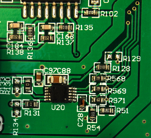
The two input offset signals are buffered in a SOIC8 device (probably an OPAMP), mounted on the bottom side between the two input frontends.
Analog Frontend
The analog frontend is realised with discrete components, and it’s actually simpler than it seems.
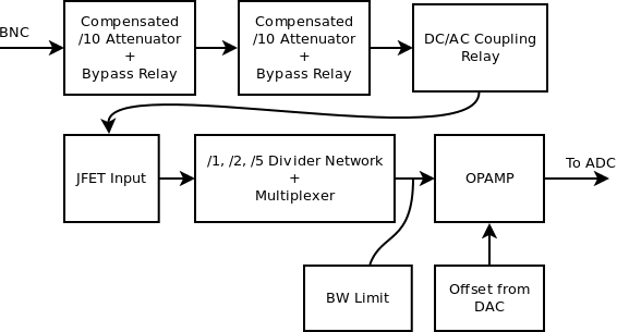
The first two relays (RL1, RL2) are used to engage or bypass two /10 attenuators into the signal path, including a tuned compensation network (that’s what the trimmable caps on the bottom side are for).
The third relay is used to bypass a reasonably big capacitor in series with the signal, after the main attenuators. This is used to implement DC or AC signal coupling.
After the AC relay, the signal is fed into a SST5912 JFET MOSFET (U33), and then into a compensated resistor divider network used to implement the usual /1 /2 /5 attenuation sequence, with the actual tap points going into another 4052 analog multiplexer.
Finally, the signal is fed into what seems to be an OPAMP (U9) to be amplified and summed to the requested offset, ready to go into the ADC multiplexer.
Also, just after the 4052, a small signal MOSFET (Q2) allows to engage a small capacitor from signal to ground, to add some sort of limited bandwidth mode.
All relays are wired into a 74HC244 octal buffer and controlled by the Cypress interface, while the analog multiplexer is wired into the CPLD directly.
Somewhere into the signal path, a couple of SOT23 diodes (Q8 and Q9) on the bottom side of the PCB are used to clamp the signal into safety limits.
Trigger Circuit
Triggering is handled by an analog comparator (U15), connected with another HEF4052 to either one of the two channels, or the external trigger.
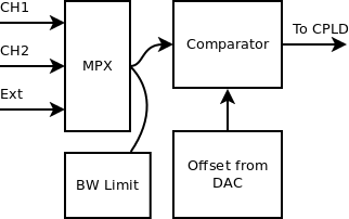
The triggering circuit also features a 2×1 pin strip input for trigger out signal, and signal MOSFET (Q4) to engage an RC filter into the signal for noise rejection. Curiously enough, the resistor is actually shorted with a 0 Ohm, so the designer decided to use the actual internal circuitry of the 4052 as part of the filtering.
Hacking and Design Limitations
The whole design is quite easy to understand, and the most interesting thing to hack is the actual CPLD clocking to allow for a higher single shot sample rate.
The stock configuration is to use a 50MHz oscillator, allowing up to 100MSPS in single channel mode. Hantek also sells a 150MSPS model, which spots two oscillators: a 50MHz and a 75MHz one (there are two slots on the PCB).
I actually tried to replace the stock oscillator with different values (75, 100 and 125MHz), and while the 75MHz works fine, with the 100 and 125MHz ones, there are some acquisition glitches at intermediate time divisions – some samples are plain wrong. This only seems to happen on the first channel if both are enabled, and seems to get worse when touching one of the two SRAM data lines, so it may just be a limitation of the PCB layout or the CPLD itself.
Anyway, I’m currently running this thing with a 125MHz oscillator, and it seems to work fine with most timebases, so that’s 250MSPS for the price of an oscillator… worth a try!
As for the software, I’m using the device in Linux with a modified version of OpenHantek. For the sample rate, the application just requests a specific clock divisor based on the hardcoded input clock value, so it’s really easy to modify the source code to specify a different value for the CPLD oscillator frequency.
Closing Considerations
That’s it! This little device does not pretend to have the performances of a real DSO, but I think it’s well worth the price considering that you can just sneak it into your laptop bag and have a basic oscilloscope with you all the time.
The best part for me is that with the OpenHantek software, it works just fine in a Linux system, and has a nice full open source software for the control application. Support for SigRok is on the way too.
The bad part is that there are not many advanced features. If you are used to fancy high-end multi giga samples per seconds scopes with tons of signal analysis and complex trigger capabilities, just forget about this and start saving money for a real device. On the other side, if you just need a basic scope that works fine under Linux, go for it!


Do you know if this runs at high speed mode or has it been set to full speed by having a 1.5k pullup resistor attached to the +data line?
Thanks
Hi John,
my DSO-2090 runs at high-speed according to the enumeration messages… Anyway, I don’t see any pull-up on USB data lines.
Fabio
Thanks for the quick reply – this seems like a good general purpose piece of kit. I’ve been looking at the OpenHantek sourcecode and it looks like a classy job of cpp code and a great way to get my feet wet using QT.
Sure, it’s quite good for the price if you just just need a basic portable scope that “just works” on Linux.
OpenHantek is a good piece of software to hack, and you’ll also find some OpenGL code in there! The only part I found a bit complicated is the low level code, but that probably comes from some older project so I guess it’s understandable. Also right now it misses the code to add low bandwidth mode and trigger HF reject functionality (implemented with the mosfet + cap after the analog mpx)… I hope to find some time to add that and contribute back in the future! :-)
Fabio
The information you have provided here is extremely useful to me. Very nice job. Thanks! USB scopes are, generally speaking, limited devices and the display software is usually junk. There’s only so much sampling bandwidth available when running off a 2.5 watt (or 5 if two connectors are used) power supply. Your taking the time to show what’s inside the 2090 convinces me that this gadget can be useful for a variety of medium speed monitoring tasks under the full PC control. Being able to use the external trigger and then pull in up to a 32kb sample for immediate analysis could be quite handy. Can I take 32k 20ns samples on two channels or am I limited to one channel for the a 32k acquisition?
I’m happy that you found it useful! :-)
If you are doing data acquisition this may really be just fine, and you can also check the sigrock backend driver for this dso, as that’s written in C from scratch and it’s bit more tidy.
That’s the source directory: http://sigrok.org/gitweb/?p=libsigrok.git;a=tree;f=hardware/hantek-dso
For the sample rate, it seems like you really get 32k per channel (up to 50 MSPS in two channel mode). Actually it looks like each SRAM chip is paired with an ADC in the CPLD firmware, as you can only get 64k sample memory in single channel only in interleave mode.
Fabio
Thanks for the tip about sigrok support! I downloaded their distribution and started digging through the Hantek dso.h and dso.c files. I came upon this disturbing note in dso.h.
/* All models have this for their “fast” mode. */
#define FRAMESIZE_SMALL 10240
Then I found this in dso.c:299 –
if (devc->framesize == FRAMESIZE_SMALL) {
…
} else {
if (devc->timebase < TIME_40us) {
sr_err("Timebase 25k pps. That’s a ridiculous limitation and certainly not caused by the 10 ns sram chips they are using. Can you confirm or refute this on your system using openhantek?
I agree, by the way, that what the sigrok folks have written is a lot easier to read than the low level openhantek code.
WordPress garbled the last comment toward the end. That’s weak.
Should be:
if (devc->framesize == FRAMESIZE_SMALL) {
…
} else {
if (devc->timebase < TIME_40us) {
sr_err("Timebase < 40us only supported with 10K buffer.");
return SR_ERR_ARG;
}
…
}
That’s weird… Right now I don’t have a working sigrok build to test (last time I tried it segfaulted :-), but openhantek does not seem to care about this limitation.
Currently I have it running at maximum sample rate (I’m running with a 125MHz oscillator from the original 50) and it seems to happily switch between 10k and 32k sample count, I even tried exporting the samples and replotting those with gnuplot and everything seems to be ok (64k samples in single channel, 2x32k in dual channel).
Maybe you can ask the sigrok developer who did the commit:
http://sigrok.org/gitweb/?p=libsigrok.git;a=commit;h=bc79e906a0911b4218b42b63b2f27fb0016c59da
The actual comment does not say much about the problem.
Maybe they should call themselves !Segrok!
Thanks for the info! If you can take a 32kb sample and see that it looks right on gnuplot then that pretty much settles the matter.
This from the previous diff of dso.c
243 /* Timebase fast (no idea what this means) */
244 if (ctx->timebase timebase > TIME_200us)
247 tmp = 4;
248 else {
249 if (ctx->framesize == FRAMESIZE_SMALL)
250 tmp = timebasefast_small[ctx->timebase – 1];
251 else
252 tmp = timebasefast_large[ctx->timebase – 1];
253 }
254 cmdstring[2] |= tmp & 0x07;
Perhaps the confusion originated when they added support for the 5200A which has a 512k deep buffer of relatively slow memory. Someone out in the cloud mentioned that it had a real limitation in that the deep buffer only worked at a very slow sample rate.
Oh well. The main reason for not putting too much effort into hacking this device is that Hantek has discontinued the product line so they won’t be available much longer. I doubt that many were sold so finding used units would be hard.
Seems like you are pushing the limits with 125mhz. The memory you link to above was spec’d at 10ns so I think you are pushing it a bit past its margins.
Do you have the Digikey or equivalent part number for your 125mhz oscillator? I’d like to try one of those or maybe the 100mhz variety. A single channel rate of 200mss sounds very attractive. You mention that there are two slots for oscillators. How is switching achieved between them? I would guess it has to be through software since one of their models (the 150?) comes with two installed (50 and 75). That might be nice info to add to your main entry.
I looked over the diffs of dso.c and dso.h. Lots of undocumented changes. I think I’ll wait until I get the board and do a little testing. Then I can talk to the developer about some real experiences.
Based on all this helpful information you have provided I think it’s worth the price to get one of these and test it.
What distro of Linux are you using? Any gotchas getting and building OpenHantek? You mentioned “hacking” but I think that had to do with changing the oscillators.
It’s always fun to read development comment! :-)
The devices on the CPLD oscillators should be the CPLD itself, SRAM and ADCs, and as you pointed out all of those should be into-spec up to 100MHz, so I’m also really surprised that it’s still working at 125MHz… But excluding some occasional glitch on channel one it seems to be fine! Oh, I also added a small heatsink on the CPLD.
The second oscillator slot seems to be used in the DSO-2150, but OpenHantek does not support that specific model, so you would have to dump the USB request to switch oscillator from the original Hantek windows application (in the 2150 flavor).
These are the Digikey p/n for the oscillator I tested:
CTX716LVCT-ND, 75MHz
CTX318LVCT-ND, 100MHz
CTX319LVCT-ND, 125MHz
For OpenHantek I’m running a Slackware -current and OpenHantek from svn, for me it built just fine with “qmake” and “make” but I rolled back to r65 because since r66 there is some issue with the trigger point at high sample rate. Did not have time to investigate on the issue yet. :-(
On the source, apart from changing the oscillator value I implemented support for controlling run-time parameters in realtime from an external device. I basically built an external USB control panel with encoders, switches and LEDs to mimic the interface of a real scope, so I just added a bunch of signals and events around in the user interface code… But that’s for another blog post (my TODO list is getting longer and longer :-).
I find it interesting that you use Slackware. It has a reputation of being a rock solid but very basic distro that doesn’t do a lot of hand holding. This especially with regard to autodependcies. I want to develop for a number of different embedded processors and Linux is new to me as a development environment. Do you think that Slackware is a good choice since I will be using gcc with a bunch of different libraries and I certainly want manual control over that.
Thanks
Well, Slackware is basic because it’s simple, so you can easily learn everything about it, and that makes it rock solid: if it breaks, it’s your fault. :-)
Anyway, my complete setup is that I use Slackware as my primary -reliable- system but I also have a paravirtualized (LXC) Ubuntu for when I need to mess up safely, and that’s where I tested sigrok (python3 is missing from Slackware).
I’m not sure I would suggest you to use it as a development system if you are not already confident with it, you would end up with much more manual control than you want!
Despite that I would definitely suggest you to try a Slackware, but only if you can dedicate some time to study the internals and mess up with the package manager before using it for anything important. There are pitfalls all over the place.
Fabio
I reread your post and I realized you didn’t say whether you replaced the 60 mhz ADC with the 100 mhz one before or after you increased the clock speed. I would be very surprised that a 60 mhz part would work at over twice its rated speed. But I suspect that’s what you found.
True?
Hi John,
You’re right, it’s not really clear on the post, but I really did the 75MHz and 100MHz mod *before* replacing the ADCs, and surprisingly it seems like the stock ones were fine, even through I did just take a quick look at the 1kHz calibration signal and ground noise if I remember correctly.
What I was expecting to happen is a rise in the base noise on the samples, but by just looking at the signals on OpenHantek I was not spotting any significant difference. My guess is that the limit is very conservative to guarantee the specs on the whole temperature range, and the thing would probably falls apart when overclocked *and* overheated. This may also change depending on the actual IC sample, so maybe I’ve just been lucky…
Anyway, I stress that at 100MHz there are sampling errors on the first channel on some time/div settings in OpenHantek (surprisingly, non the fastest ones), and at 125MHz the same seems to happen but only at the fastest rate. Channel two seems to work fine on the whole range.
The weird thing is that the glitch at 100MHz appeared to be software related somehow: those were occasionally going away if switching forward and backward with the time/div setting (I know, sounds crazy) so I wanted to try get a better understanding of what’s going on at low level but got held back by the actual OpenHantek low level code.
As for the glitches at 125MHz, that may just be the SRAM pushed well over its limits… but still, channel 2 is fine!
Hi Guys,
sigrok checking in here. I wrote the hantek-dso driver, but haven’t messed with it in a while. The 10k buffer mode (“fast” mode) is common to all five models in that series. It’s equivalent to what (low-end) scopes display on the built-in LCD: a low resolution representation of the signal.
I got the protocol from the hantekdso project, which is also where openhantek got it. This was sort of incomplete though, and got a couple of things wrong IIRC. There may yet be some things wrong with my implementation as well, as it’s only been tested by myself as far as I know — could really use more people to help out with this!
I’d love it if you guys would join #sigrok on irc.freenode.net, where all the development chatter is. It might even motivate me to finish support for the DSO-5200A, which is sitting on my desk unused.
Fabio, please file a bug report for that segfault you saw. We take these very seriously!
Hi Bert,
so that mode is available on all models, but maybe not all of those needs to force it at higher sample rate as John pointed out.
I’ll try to help testing the 2090 with sigrok in the near future, as the project looks really good! I’m sure you take bug reports seriously… but first I have to take my time to fill a serious bug report! ;-) (and I would rather send a patch instead…)
Fabio
Hi Bert,
Please don’t take offense at my !SeGrok! crack above – just my misguided sense of humor. I’m a sucker for a bad pun. However, like Fabio, be assured that I am very appreciative for all your efforts!
Just got shipping confirmation for a 2090 I recently ordered and I’ll be happy to contribute any information I can after I get it set up.
I’ll intercept the USB setup packets and find out more about the “fast” and “slow” modes. I was thinking that the “fast” mode might allow the data to be uploaded while a new sample was being acquired but that would require dual ported memory and twice the clock rate on the CPLD so that’s not gonna work.
Thanks for signing in,
John
I think what will happen is the buffer will get overwritten while it’s being transferred via USB, and there’s no way to avoid it.
It’s basically a circular buffer. When acquisition is active, it continually gets filled with samples, wrapping around to the start when it’s full. When the trigger fires, up to half the horizontal trigger position’s worth is read, then it stops acquisition. What the host side receives is thus the full buffer, but the trigger point in that buffer doesn’t correspond to sample 0 or wherever the horizontal trigger position was set — it’s at some random point where the buffer index happened to be.
That trigger point is sent to the host via CMD_GET_CAPTURESTATE, encoded in some way that’s no doubt easy in hardware, but looks very strange in software (dso.c: dso_get_capturestate).
The way it treats that buffer, I just don’t think there’s any way to be sure when which part of it will get overwritten with new sample data.
You may be right. I think I went with the logic that I found in the hantekdso code, and didn’t actually test whether it could do better — an exhaustive test would be a good idea here. Feel free to use the sigrok wiki to document this sort of stuff, too.
Hi, just a quick update on sigrok: I grabbed the latest git trees and rebuilt everything and now it just works, well done! I guess I just landed on a buggy commit last time.
This is what I’ve used to test:
sigrok-cli -l 3 -d hantek-dso –frames 1 –output-format analog –config coupling=DC:vdiv=50mV:timebase=4ms –probes CH1
I actually find sigrok-cli a bit unfrendly for analog, currently it silently exits if you don’t specify the correct output-format, but I guess that most analog stuff is still WiP.
Also, I tried dropping the small frame + timebase sanity check and it still works fine for me, so that may be just enabled for the 52xx series DSOs.
The project is awesome and I really appreciate sigrok developers mission of supporting every T&M device in the world! :-)
Fabio
Fabio,
Does that pin header at the bottom of the board in your top picture look like a JTAG connector for the CPLD? That would be nice.
Ciao,
John
Hi John,
The 6×2 header is marked as “Option I/O for second design”, so that’s probably just generic I/Os, but the 6×1 header above looks like some well defined pinout, so that’s probably the CPLD jtag.
There are some high res pictures of the layout here http://www.artem.ru/cgi-bin/photo?c=l&cid=115 if you are interested.
Cheers,
Fabio
Thanks for the link. I looked at the pix and was interested to note that the 2150 has a trigger relay whereas your 2090 does not. I wonder why? Any ideas?
The case has a grill on the bottom under the CPLD to allow air flow but nothing on the top. Might be a good idea to put a few holes over the CPLD and the ADCs since they are the hotties. Especially since you are overclocking and you need a place for your heatsink to send the hot air. There seems to be some room between the board and the edge of case so that air from the bottom can come up around OK.
Hi John,
That relay looks like another /10 attenuator for the trigger line… I guess that’s mounted only on the 2150 for no specific reason. You can probably just fit one and the missing resistors on the 2090 (or just use an inline BNC attenuator).
Some additional holes may be a good idea, the bottom grill is probably not much effective, but I’ll try to take some temperature measurement before cutting holes in the whole thing… If it’s still in specs I just don’t care :-)
Thanks for the update about the product line!
It’s hard to know what “specs” are when you are pushing an ADC to twice its rating. The production line might have a great day when your 60 mhz part was made and ended up marking a 100 mhz part as a 60 because they had a quota to fill. I know you have 100 mhz parts now but other folks may decide to do the speedup without the ADC upgrade and putting some small heat sinks on them along with a few small holes in the top case might improve performance. I don’t know how ADCs fail when they overheat. And I also don’t know if they are damaged by being run too hot. Probably not, depending on how hot and how long. But I suspect that slower ADCs and CPLDs draw more current at high clock rates and, of course, USB has some real limitations there. I plan to use both usb connectors at high sampling rates so I can supply ten watts to the board. Otherwise the glitches from too little power could cause quite mysterious ailments. The CPLD alone draws 250 milliamps at 94 mhz under “typical” conditions. Granted that the CPLD on this thing probably isn’t doing very much. It’s a DMA controller and only has to increment an address counter and route 16 bits of data every clock cycle.
Just some thoughts. If anyone does the speedup and has strange readings I’d suggest taking the top off blowing some air over it with a small cpu fant and letting it run that way to see if it helps. If so then maybe some holes would be helpful.
Well, as long as you go out of spec you can’t really say anything, I just tested pushing it and somehow is (partially :-) working. Anyway, the ADC08100 datasheet actually mention 125MHz operation, but it’s characterized at 100MHz.
Temperature… I think that temperature just shorten the component life, the specified maximum is +85, if you are under that it should be ok.
The power consumption from USB was about 560mA worst case in the stock configuration, I have to take an updated measurement as soon as I get back my USB measurement board.
About the glitches, I did not notice it getting worse when heating up, but it may make sense!
My above comment that Hantek is discontinuing the product line is apparently not true. I checked back in on their website and NOW the product list has the 2000 and 5000 series scopes listed on the third page. Two days ago that was not the case. I don’t know if it was just a glitch in their web page database or what but I wanted to let you all know since it really is a nice little board for the price and I don’t want to discourage people from buying one.
Hi Fabio,
I got the 2090 and have been playing with it using the Windows software. I have a glitch that I’ll try to describe and perhaps you can check it on your board using either or both Windows and Linux software.
I’m viewing the calibration waveform simultaneously with a Rigol 1052A and the 2090. The Rigol never sees the glitch so that’s evidence the calibration square wave isn’t at fault.
I’ll going to give specific settings here but frankly I can see this glitch at many different settings. The main requirement is that the sweep has to be fast enough that I only see one edge (rising or falling).
I set the time base to 10us and the vertical to 1 volt dc coupled. Trigger normal on – edge and trigger at 1.5 volts (it’s a 2 volt pp squarewave on mine). The acquisition buffer is 10k – Hantek software won’t allow the longer buffers at less than 40 us. per division. Channel 1 or channel 2 – doesn’t seem to matter. When I overlay both channels the glitch shows up identically on both.
What I see is an occasional stairstep down to 1 volt that occurs 20 us or so to the left of the trigger point. It’s not consistently 20 us – sometimes or sometimes less but most often 20 us. Sometimes I see the whole trace on the left side of the trigger point at 1 volt.
In other words I am seeing a voltage level of 1 volt **at** the trigger point. But the trigger is set to fire at 1.5 volts and that happens at analog front end. Clearly I’m seeing an artefact since otherwise it would trigger on the visible falling edge and see a stairstep down and to the right of the screen.
I find this disturbing because seeing accurate representation of pulse edges is a common use for me. I certainly don’t want to have to constantly wonder if the glitch I see is something the scope is doing.
Wish I could send you a screen shot but it’s devilishly hard to capture since it’s a phantom and I can’t set the trigger to fire on something the trigger can’t see.
You mentioned glitches several times and I’m starting to think that maybe what you’re seeing is this.
I never see a glitch if I am showing three edges on the screen.
I’m running 7.0.0.3 Hantek software using newer drivers than what Haag’s software downloads from the Hantek site. I don’t think that matters – this doesn’t seem like a low level usb driver issue. Most likely a flaky CPLD implementation – and that’s pretty much out of bounds territory. I don’t think anyone wants to mess around with VHDL or Verilog for an old and expensive CPLD.
I’ll be really interested in what you observe,
John
Me again,
I forgot that I set the averages to 2! That’s why I was seeing a stairstep. It was averaging two waveforms and only one had the glitch so the average of the two would be halfway. Doh!
When I set acquisition to normal I see a conventional glitch – the waveform jitters to the left of the trigger point. I suspect this is what you are seeing too. It looks like the scope isn’t reporting the correct trigger point in the returned data sample. After looking at the convoluted coding required to figure out the trigger point it wouldn’t surprise me if that’s where the glitch is happening.
Let me know,
John
Hi,
My “overclocking” glitches are really out of scale points on an otherwise correct waveform, and just appears as spikes… I’m quite confident that those are just a digital signal pushed over the limits.
What you describe is basically the correct waveform skipping before the trigger point for as much as a couple of division, I don’t really remember having seen that at all, through I found out that the triggering circuit is not too precise and tends to jitter a bit when pushed too hard (nanoseconds scale). Could you estimate how often do you see the wrong waveform when sampling the 1kHz test signal?
This may be an issue with that crazy trigger point conversion logic (I add myself to the list of people who don’t understand what’s behind it :-), but as Bert said, it may be fixable.
I’ll not have access to my hardware for a week or so, but I’ll try to make some test as soon as i get it back.
I’ve seen that glitch as well, with the original Hantek software. If you take as a hypothesis that the convoluted trigger recovery code has a slight error that causes it, and that this is showing up in every implementation, it might be fixable. This doesn’t seem too far-fetched to me: it’s an algorithm I don’t get at all, hence I distrust it :-)
So… does anyone understand the reasoning behind it? This might bring clarity…
I don’t have a Linux box set up yet but here’s an easy test for those who do:
OpenHantek source control.cpp : 299
int Control::getCaptureState() {
int errorCode;
errorCode = this->device->bulkCommand(this->command[COMMAND_GETCAPTURESTATE], 1);
if(errorCode device->bulkRead(response.data(), response.getSize());
if(errorCode triggerPoint = this->calculateTriggerPoint(response.getTriggerPoint());
return (int) response.getCaptureState();
}
Remove the calculateTriggerPoint(xxx) call and just use what’s returned. I have a sneaky suspicion that nothing much will change.
My guess is that there’s a board level implementation error in the CPLD – 8051 interaction that’s causing the offset to be calculated incorrectly. Various programmers have tried their hand at imagining a cure for what’s incurable. Here’s another programmer’s (HantekDSO hantekdsoio.c : 687) idea of how to handle the problem that makes my head hurt –
int HantekDSOIO::tpTransform(unsigned *triggerPoint)
{
unsigned tp1 = *triggerPoint;
unsigned tp2 = 1;
while(tp1 > 0) {
tp1 >>= 1;
tp2 < var_2)
{
var_C = (var_1 – var_2 + 1)/2 + var_10;
if ((var_C > *triggerPoint) == flag)
{
if (!flag)
{
var_10 = var_C;
}
var_1 = (var_1 + var_2 – 1)/2;
flag = true;
}
else
{
if (flag)
{
var_10 = var_C;
}
var_2 = (var_2 + var_1 + 1)/2;
flag = false;
}
}
*triggerPoint = var_2;
return 0;
I don’t have the energy to check if the two methods yield identical outcomes but I doubt it. It’s pretty clear that they were arrived at independently.
If the returned buffer offset were correct or off by a fixed amount then there wouldn’t have been this amount of creative programming effort to find a way to fix the problem. I am pretty sure there’s a real but occasional problem with the returned offset value. It seems to be a problem that tends to make the buffer pointer higher than it should be and often by fixed and not too great amounts.
WordPress isn’t programmer friendly so I hope these excerpts are readable. If you know of any way to insert box clips of programming text please let me know.
That code is evil! :-)
You may put it on pastebin and just link it in the comment but there is definitely something going on there.
I’ll try pastebin here:
Sad. The pastebin link didn’t show up – is there a special way to paste in the link? I just copied the Javascript embedding link and pasted it in the body of the comment.
Just copying the url should work, that should be the function:
http://pastebin.com/h13r2mu4
If we can find a way to reproduce the problem with sigrok maybe we can fix it on their driver and move on the sigrok mailing list, I think that’s the best place to discuss code and for sure the more readable one :-)
It’s occurred to me that sigrok is perhaps even the easiest way to dig deeper into this, as you can trivially grab a frame at a time and feed it into whatever on the shell, for later analysis by “raw” sample. Indeed, that’s the only thing you can do with it right now, for lack of an oscilloscope client ;-)
You might hack things so the trigger point value (before processing by strange algorithm) is also output, and see if there’s a correlation there.
That’s also what I had in mind, could be fun! :-)
Anyway, in the meantime I quickly put together a comparison with the two functions and curiously enough – unless I’m missing anything – the result is the same!
Code here: http://pastebin.com/kp5U9wCP
Yeah, I did the comparison as well at the time. I went with the openhantek version because it was obviously cleaner.
My conclusion was that the hantekdso guy transcribed the function from machine code he found in the vendor software’s executable without understanding it, hence the var_10 etc names. I don’t particularly see how you’d derive the openhantek code from that, though, so perhaps that guy actually understands it.
What really puzzles me is the function’s behavior at points like 10000000. The next value will be 11111111! If we’re talking about offsets into a buffer then that’s a huge jump. And the next value will become 10101010. These are crazy to my eyes. We need to remember that this is jumping around in a linear array of bytes. If I’m understanding this right, it’s saying, if the DSO passed me 10000000 as the position of the triggerpoint in the data buffer then it’s REALLY at 11111111. And if it passed me 11111111 it’s REALLY at 10101010. I’m using eight bit values but it holds for 16 bit as well. I just don’t see how that can work. Normally these extreme cases aren’t encountered but there will be common cases where a 1 bit is followed by four or more zeroes and this will still result in a fairly big jump.
Probably the returned data pointer doesn’t change that much from one acq to the next as long as the trigger position on the scope isn’t changed. But if the algorithm is so wrong I would expect to see the triggered edge jump around as I manually move the triggerpoint along sample. I don’t see anything like that and that puzzles me.
Your observation about the hantekdso guy translating machine code language is interesting. But maybe he was duplicating what is possibly a bogus method to begin with. Have to keep in mind that Hantek probably doesn’t hire the best programmers in the world – and the board may have been designed by a third party. Who knows?
I do notice that FreeDSO originally used Haag’s method but then commented it out.
See: http://pastebin.com/J636VLzT
Oliver Haag’s code can be mindbendingly indirect ( pointers to pointers to pointers ) but there’s no doubt in my mind that he has a keen mind. I sent him an email several days ago asking for a clarification about this transform and how he arrived at it but I haven’t heard back yet. It wouldn’t surprise me that he could look at the output from the hantekdso algorithm and deduce a simplification.
I think your idea about using the sigrok code base and building a test harness to try out various ideas is excellent and I think I’ll go that direction. Originally I was planning on learning some QT and C++ using Oliver’s code as a starting point. But this convoluted transform has created an itch I’ve got to scratch – you sure know how to get back at me for my wisecracks, Bert!
There are two issues here. The first is the XOR & shift transform and its rationale. The second is the erratic triggering. I don’t think they’re related.
I believe the transform is required and that it is done as an easy to implement XOR obfuscation technique. Having said that, there is no reason that I can think of why Hantek would want to do this – after all, they sell hardware and give away software. If anything they should publish the low level interface to the board and make it easy to work with. Their product protection is the code in the CPLD. It’s stored in flash memory inside the chip and I don’t think it can be read back out. Why wouldn’t they want to encourage the use of open software to sell their product? Crazy. Nutty.
The inverse of the this XOR shift operation is very simple – just start on the left side and shift right. So I think the 8051 code encrypts the trigger position and the Hantek display software decrypts it. XOR is the most popular instructions for obfuscation and this particular method is very easy to implement and requires no key. That Oliver Haag saw what it was is pretty amazing. I googled around for other descriptions of it and didn’t find any.
However, I don’t think this has anything to do with the triggering glitch.
The CPLD is basically working like a direct memory access controller (DMA). Data comes in through the ADCs and is stored sequentially in RAM, round robin fashion. It runs continously when the scope is enabled. I’m going to describe how I think the triggered mode works because that’s the most commonly used and that’s where I am seeing the horizontal jitter.
The display software sets the hardware up with a trigger level, a buffer size and a trigger position. This information gets sent to the 8051 that is running the downloaded 8051 driver. It uses that info to set up the CPLD and is responsible for reading the waveforms and trigger data back to the PC after an acquisition.
The TriggerCounter is a downcounter set to the trigger percent of the current buffer size. Usually it’s a 10K buffer so I’ll use that for the explanation. If it’s a 50% trigger then the counter is set to 5000 counts.
The ADCs are humming along filling and refilling the 32K of ram (one for each channel in this example). A trigger event occurs and two things happen.
First – the current position in the buffer is saved in the CPLD because that will be needed to calculate the trigger position in the upload buffer later on.
Second – the TriggerCounter is activated and counts to zero. The CPLD stops acquiring data and signals the 8051 that a measurement is ready.
The 8051 knows how large the buffer is so it subtracts from the current position (modulo 32k of course) by 10K to get to the start of the captured waveform. It then subtracts that starting address from the trigger address saved when the trigger occurred. This is the trigger index sent along with the uploaded waveform.
The waveform and trigger index are now uploaded. I believe the 8051 transforms the trigger index before sending it using the inverse XOR shift technique. This would all be done in the assembler code that gets downloaded on startup so it’s possible to disassemble the binary and examine if required.
The question is – what would cause the calculated waveform index to be too big (generally) by a factor that seems fairly consistent? And what accounts for the jitter being much more pronounced at the default (50%) trigger point? When I move the trigger slightly to the left the jitter is much diminished.
I think that removing the call to the transform in OpenHantek will make the trigger much more erratic – especially when moving the trigger point around. If I’m wrong that’s fine but this proposal has the virtue of being a lazy man’s test – and I love those. Remove a few characters, recompile and run. If it turns out, as I expect, that removing it makes the wave even more jumpy then I think it strong evidence that this transform is obfuscation, is required and we can stop thinking about it.
The next step would be to move over to the sigrok code base and write up some simple tests.
Again, just to keep some perspective here. The Altera CPLD Hantek uses here is now deprecated and no longer in production. Hantek has moved on to a new line with a different case though with very similar specs and prices. It may not be worth putting a lot of effort into a product that won’t be available much longer.
(guys, we really need to switch to the sigrok mailing list or even direct email, I need quoting!)
Aside from your other conclusions, it’s not the 8051 (FX2) that’s doing this trigger point encoding — it’s the CPLD.
Simply put, the FX2 only handles control requests in this protocol (in sigrok hantek-dso/dso.h it’s the “control_requests” enum); the commands going via endpoint 2 (“dso_commands” enum) go to the CPLD without the FX2’s 8051 getting involved. Both EP2 and 6 are setup as FIFO-only endpoints.
(yes, I disassembled the firmware)
Well I’ve put some thoughts on the addressing and was thinking: maybe they just scrambled the addresses used in the circular buffer to avoid EMC issues with many high frequency digital lines switching at the same time, such as preventing a fast edge on all address lines when stepping – let’s say – from 0x0fff to 0x1000… some sort of spread spectrum. That’s a dumb 2 layer board after all, I would be surprised if it passes an emission test at all.
Maybe this stuff is obvious for a CPLD/FPGA expert and the sequence is very efficient in a programmable logic.
Beside that, I agree with Bert on switching to the sigrok ML, wordpress comments are driving this crazy! :-)
I tried drawing up a logic circuit and the only thing I could come up with required a chain of fifteen inversion gates at the LSB for a 16bit integer. Even a 2ns gate propagation delay would make 125 mhz operation impossible. This sequence transform is recursive so the only other way I could think of is to use a lookup table – or maybe partial lookup tables hooked together with some logic gates. But that’s a totally uninformed opinion.
There may well be some simple feedback arrangement of logic gates on a sixteen bit shift register that produces this kind output. But I still can’t imagine how one avoids the need to ripple a change down the whole chain to the LSB when a 1 bit is left shifted into the MSB position of a register filled with trailing zeros. Seems like that would cause the same propagation delays as using logic gates on outputs of a conventional counter as described above. The tapped outputs of the shift register are what’s used to address the ram – they have to get stable before a data read edge arrives.
The spread spectrum idea is interesting. There’s a lot of switching going on any time a 10…0 pattern is encountered since the next state becomes 11…1. However, that may be the only case where a lot of bits change at once —
As I say below, my interest waned after Bert set me straight about the transform being done in the CPLD. Nothing to be done about it in that case and it makes the above speculations academic.
In my dramatically reduced “free time” (see comment to Bert below) I’ll use the sigrok tools to see if I can capture a few errant buffers full of data along with the capture states and see if it shows up anything. If I capture anything interesting I’ll sign up at sigrok and share my findings.
Thanks for all the good conversation and useful information!
John
John,
Will you join the mailing list? This conversation is just gettting interesting :-)
Thanks for the invitation, Bert, it’s much appreciated. However, I just got a (really really boring) contract that’s going to keep me underwater for a few weeks so I’d best wait until that’s completed before I let an interesting conversation like this compete for my attention. I anticipate reconnecting in the near future.
I was disappointed to learn from you that the 8051 on the FX2 is not mediating between the CPLD and the PC. That means that the trigger point is, as you say, encoded by the CPLD and that code is way past what I want or am competent to comprehend and modify even if it were accessible – and it doesn’t look to be. Even if it were and free development tools were available, I’d rather learn VHDL or Verilog (not high on my list of fun things), on a more modern chip like a Spartan 3.
Also – as you may have gleaned from my above comment to Fabio about distros – I’m barely able to get things done when it comes to Linux and there’s a shin bashing learning curve involved in getting to the point where my legs aren’t dripping blood after every piddle ass task.
I want to thank both you and Fabio for this informative conversation. I’ve learned a great deal about the 2090 and I intend to learn a lot more about it by using your excellent sigrok tools. Being able to command it from a cli is great!!!
Warm regards,
John
Hy guys, small update from me: I got back my 2090 but I can’t really reproduce the issue with openhantek (not tried yet with sigrok).
This is the signal I see:
and I can’t see it moving from the trigger setpoint.
John: do you want me to try some specific configuration?
For completeness, this is the glitch I see at full speed when overclocked (2x125MSPS interleave):
I also tried to comment out the trigger point conversion but you can image what the result is. :-)
Cheers,
Fabio
Hi Fabio,
I only see the bad triggering when the waveform is expanded so only the trigger edge shows on the screen. Your waveform is showing several edges. Try setting the scope to 10 us and leave the trigger point at 50 percent like you have it in the picture. The Hantek screws up at 50% but stabilizes when the trigger point is moved slightly off center either way. The failure almost always shows up on the left side as and edge that arrives ahead of the actual trigger condition.
John
Nope, still no visible glitches (10us, trigger 50%, but also tried many other random configurations). Let us know if you manage to give openhantek a try! :-)
I am disappointed in the Hantek software. The triggering is erratic. The memory depth is crippled at settings under 40 us per division. The methods provided to zoom in and move around in the waveform are primitive and clumsy. The overall look and feel is from the 1990s. Ugh!
I would like to play around with OpenHantek – it looks like a very classy piece of code and I’d learn a lot. But the problem for me is that I require stable basic operation under XP. I can live with the crippled memory depth and a clumsy and ugly interface but I can’t live with waveform jitter. If I’m looking at a debug pulse that’s referenced to an offscreen trigger I can’t be sure if any jitter I see is a Hantek artefact or a problem in my code.
An acquaintance of mine has just offered me his Rigol DS1052 at a great discount since he just got a DS2072. Given the above problems I am going to return the 2090 for a refund and buy the Rigol. I’ve been playing around with it a little and it’s a wonderful scope. The megabyte of memory depth makes capturing debug timing information a breeze. The triggering is rock solid. Everything works – and I get 10 to 20 times the sampling rate of the 2090 as a bonus.
I’ve really enjoyed the time spent here discussing the Hantek and I would keep it if I weren’t so tied to some Windows development tools and could transition to Linux.
Thanks for all the useful information and good conversation! It’s been a pleasure talking with you and Bert. And, even though it’s not going to work out for me, I believe the Hantek is a great little USB scope for someone who can run it under OpenHantek or sigrok software. It has some nice features and performance for its price.
All the Best,
John
Hi guys,
I’m trying to fix my 5200A. One day I connected it to the pc and the red led started to blink, but it wouldn’t change into green. When I run the software it freezes the computer.
If I disconnect the usb cable the software loads normally. I described the problem in more detail here: http://goo.gl/uWyv61
I tried to load some generic firmware with cypress USB console and it loaded it with no problem so I guess usb controller chip is ok.
What would you guys suggest to try next? I have Saleae logic analyser…
Tnx.
Frenky
Hey Frenky,
You should start by verifying that at least power supplies and oscillators are working and search for some sign of life from the cypress (if it’s talking with the PC it’s probably ok) and the FPGA (anything moving on any output pin).
Apart from those there’s not really much you can do… My guess would be that the FPGA failed and it’s blocking USB communication as well (you mention that the cypress on its own seems to work).
Fabio
Tnx. I measured all the power rails and everything seem s to be ok. On one side its +5, -5V and on the other side I got 3.3V and 1.2V. When I found 1.2V I was sure that this is the faulty 3.3V but then I found datasheet for DC/DC converter and it actually is 1.2V. http://goo.gl/ylpCZX
So now I will test 50Mhz oscilator and other signals around FPGA.
Tnx for help.
I just had a similar problem. Sometimes my device worked, sometimes it didn’t (red blinking led). Especially when it got warm, it gave me the red blinking led. So I used coolant spray on the pcb to locate the problem. I found some suspicious looking soldering joints around the +/- 5V regulator circuit. After resoldering them everything works.
C.K.
Well done!
Hi Fabio:
I am writing to you almost as a last resort!
My this year birthday present was a DSO2090. I am a newbie to Linux and I am using Linux Mint 14 (Ubuntu 12.10 underneath) since this summer, my wife “upgraded” my laptop to W8.
By the way DSO2090 software does not installs on W8; a not digitally signed message stops the installation (hate Windows 8!). But I have a VirtualBox VM with WXP where it installed nicely. I share the same VM on Linux and it runs fine also.
But native on Linux I have not been able to get any result; To me it looks that OpenHantek PPA was moved or erased from the Ubuntu repositories.
I then tried to build and install but I never can go further than ./configure. I was able to solve some of the errors installing KDE packages and changing names of files but still no avail. The scripts are quite old and many things have changed since them were written.
I am on the verge of giving up!
I wonder if you can help me not to do so.
Thanks in advance.
NB
Hi Nestor, no idea about windows or PPAs, but you should be able to grab the latest sources from the subversion repository and build the package from source using “qmake” followed by “make” – install any dependency as needed.
Cheers,
Fabio
Hi Fabio:
I make it work on Windows 8 last nigth.
Still I want to get it working on Linux.
Will try again later today and let you know.
PPAs are Linux stuff. First time I saw it was at the OpenHantek website.
Thanks
Update:
OpenHantek installed on Linux.
Still udev or what else should recognize the DSO not working.
I do not know what I am doing wrong!
Tomorrow I will post more details…
NB
Ok, but you should really open a thread on the openhantek forum here: http://www.openhantek.org/forum/
Fabio
OK
NB
It is working!
Only one caveat: It needs root privileges.
Can I get rid of this?
NB
Hi Nestor!
So, you can either use sudo or add a file in /etc/udev/rules.d with a line like this:
ATTRS{idVendor}==”04b5″, ATTRS{idProduct}==”2090″, MODE=”0660″, GROUP=”plugdev”
Assuming that your user is in the plugdev group.
Sorry to hear about the openhantek forum… You should take it as a best effort thing! :-)
Fabio
Hi Fabio,
Yes the openhantek forum maybe is a best effort… But then put a note to let everyone be aware of the delays. I am pretty sure that many times, times is short…
Thanks for your advice! I noted that inside the 90.hantek.rules was the same sentence but with a minor change: instead of ATTRS was SYSFS
Changing did the trick and now it runs without sudo o run as administrator.
But still I wonder why!
Some questions:
1- You said: “This is actually useful to operate the ADCs in interleaved mode on the same channel,..” Can I operate it this way?
2- It is worth to run it at 75MHz? (To be on the safe side but to increase the sample rate.)
3- You said: “I’m using the device in Linux with a modified version of OpenHantek…” Any advantages? Could I try your modified version?
Regards
NB
Hi Nestor,
SYSFS should be a deprecated syntax of udev rules, glad that it’s working now. The svn version seems to be correct though.
As for the questions:
1 – Sure, that kicks in automatically when you have only one active channel and try to use 100MSPS. You should notice that the noise floor rises up due to offset in the ADCs, and the sample rate goes back to 50MSPS if you enable the second channel.
2 – It’s up to you, the crystal is really cheap but the 1.5x increment in sample rate is not a huge deal.
3 – Yes, that the sample rate and time base are displayed correctly! :-) Just change the values for this->specification.samplerate… in Control::connectDevice() (that’s in control.cpp) and rebuild.
Fabio
By the way the openhantek forum is a joke!
NB
Pingback: Dobrica Pavlinušić's Weblog / Blog
Hi,
Most of what you guys are talking about is over my head, but I have an 8060 that is dead. I would like to fix it or is it just a waste of time.
Thanks,
Craig
hello sorry to dig up old thread, but, can you tell me the U12 part number? and i am assuming U33 & U34 are the same “SST5912” right? as i killed my DSO few years back and just decided to revive them…
Hi! From the high res picture on sigrok website all of those seems to be SST5912 (http://sigrok.org/wiki/File:Dso2090-jfet-small.jpg).
Ciao Fabio.
I am kind of ashamed posting this question reading the level of the topics already posted. I am a amateur radio fan and just bought a used Hantek DSO-2090. as a Linux user, I first looked for the proper software and found OpenHantek. Unfortunately, and even thought I followed the instructions carefully, I never managed to install the software on my Xubuntu (3.13 kernel w. XFCE), seems that the previous repository is not working anymore.
Any advise will be greatly appreciated (noob level, if possible.
Greets from Peru, de OA4CKN.
Hi Francisco, which repo are you using? My fork from when I posted this (https://github.com/fabiobaltieri/openhantek) seems to still builds fine on the current ubuntu LTS:
$ git clone https://github.com/fabiobaltieri/openhantek
$ cd openhantek/
$ qmake
$ make
[lot of noise, no errors]
What specific error you get?
Hi Fabio, well, instead on persisting with XUbuntu, I took the other laptop with Fedora 20. Finally achieved to compile and launch, then extracted the .hex files and loaded the drivers. Still having the “Insufficient permission” but worked around with “su”. Finally it work but I noted that the calibration tip reads as 2.5kHz instead of the supposed 1kHz. In other words, vertical measure is fine, horizontal is not. Should I need to calibrate somewhere?
Thanks in advance! :-)
Good it went through! If you are using my repo there is a clock hack on it, just revert the last commit (git revert HEAD) and rebuild.
Very good description of this device, thanks a lot. I did have some issues with the fabiobaltieri branch of the software, though. Most importantly, the spectrum did not work for me, and the software was not entirely stable. Also, the firmware extract are missing some configure file, so I had to build it “manually”. When I switched to the original openhantek code base from sourceforge, everything worked as it should. The only little issue (which I can live with) is that there is a DC offset, especially on channel 1.
Hi Egil, my branch is a git-svn clone of the original with the 125MHz hack and some remote control logic, it should not have any difference on what you mentioned… that said I was missing some updates since I cloned, so I just merged and pushed the last revision (only build tested though, I don’t have my hantek right now). Anyway, I don’t really maintain that branch, just use the official one if it works for you.
Thanks so much for getting back. It could of course have been me also messing up things in my build, for whatever reason. Anyway, I have now done some updates and bugfixes to the software, branched from the Dec 4 2012 version. Have not heard back from Oliver yet, and the openhantek.org site is pretty broken, so not sure what to do with it yet. My ChangeLog digest is:
Implement bandwidth limiting filter on both channels and HF rejection filter on trigger
Implement calibration for fastrate, including DSO-2090.
It seems the DSO-2090 definitely supports it, and the offical Hantek software also uses it.
This much improves the readings for single channel timebases <= 10uS.
Bugfix: When setting an offset slider at the very top of the scope, afterwards it becomes
hard to move the slider down again.
Bugfix: Made EXT trigger source selection actually work, and remove the EXT/10 mode
(which I doubt exists, at least on the DSO-2090).
Add slider for external trigger level, and only make the slider for the current active trigger
source visible at any one time (which seems like the logical thing).
Disable GND setting since it is not yet implemented
My todo-list says:
* Implement ROLL mode properly (it really does not work now)
* Implement GND
There are also a few things on my nice-to-have list. If anyone are interested in testing or contributing, please tell.
Oh good stuff… I remember playing with the bwlimit thingy, the code was there but not mapped to any control… it was quite useful, especially on the trigger channel. If the maintainer does not answer just git clone the repo and push it on github, it sounds like you have some useful stuff. BTW I tested on my HEAD and it seems to work fine, including rolling mode (it never unwinds though…).
Really awesome article. Especially the part about the oscillator. I like to poke things a bit :)
But even with the 75Mhz oscillator the stock ADC would be clocked at more than twice its specification (if i get it right). Does that work? Or is the 8100 needed to pull that trick? Could not find one so far :)
Hey Stefan, the original p/n for the ADC is rated to 60MSPS, and with the stock oscillator they would overclock it to 75Mhz (150MSPS is achieved using both ADC in interleave mode, therefore only works in single channel mode). They probably found this to be working well enough. By pushing the ADC beyond specs you would get a performance degradation, the 60MSPS part number is obviously only characterized withing its range, but if you look at the datasheet in the graph part (“Typical Performance Characteristics”) you can see which performance figures degrades with the input clock. The graphs are usually only plotted up to 65 or 70MHz, but you can try to extrapolate the figure at 75MHz.
That said, I think that they just put the cheaper part of the board and saw that it’s good enough for a cheap scope. Those figures probably only matters if your are building something more high end (think of having the ADC part of a more complex signal processing chain)…
Oh. Yes. Sure :)
Thanks. I will definitely try it out with the 75Mhz.
I just bought one of these, but I’m not sure I got correctly the sequence of steps for doing the modifications.
Could someone who got it working, write down a list for each individual enhancement?
Is it also known if some new (incompatible?) HW revision has been produced in the meanwhile?
The original article is now 3 y.o. What are the HW revisions that are known to work?
Will it be necessary to use other SW than sigrok, to leverage the modifications?
I would prefer to stick to sigrok
Hey Igor, I don’t know of any hw revisions about this. For the mod you just have to swap the oscillator for a faster one, if you don’t touch the software you are just going to get half of the real scale on the time/division.
Hi Fabio, thanks for the quick reply. After I get it working, I’ll check with the sigrok devs if it’s possible to introduce a separate model, something like dso-2090-x2 where the scale is expressed correctly. This might be an acceptable way to have the modded scope supported by mainline sigrok.
My DSO2150 has never had traces that match when hooked to the same signal, Hantek has never given me any assistance, maybe you can. I use it on DC mostly and I would like to be able to have the traces match for comparisons. I have uploaded screen shots to https://drive.google.com/folderview?id=0ByQAhs0e-yF9VlF5SDF5Z3NqVWM&usp=sharing so you can see whats happening. I wonder if the soft ware can be modified to correct this or what can be adjusted on the DSO2150 .
Thanks,
Jeff
Hi, from what I recall the Hantek application had some calibration option, but I don’t think you can adjust it in the scope itself.
Thank You very much for this paper as it helps me to repair my scope. There was failed step up converter which recover +5V supply for analogue part. Temporary is working with built in converter from power bank.
Hello, thank you for the article.
I have this oscilloscope and it was working fine, but now i can’t see nothing coming out from the board, it turns on and the led is blinking like is transmitting the signal through the usb but I’m not able to see anything in my screen, although by times I get to see a really tiny signal (with 20.0 nS) also I tried with the calibration signal that is working fine (tested with another oscilloscope) but nothing on the screen.
Would you happen to know about this issue? or do you know a way to make like a factory reset, or some sort of steps to check the board.
Thank you
Hi Fabrizio… not really, the device does not have any persistent firmware apart from the loader in the cypress so there’s no such thing as a factory reset.
Hello! I have got a big problem. I have got DSO-2090. It was overloaded by 230 V AC. This device is not working and PC is faulty. 230 V electrical fuse disconnected. Now when I attached DSO to any PC then DSO blocked PC. DSO is short circuit. Can you repair it ? What can be wrong? Thanks : Andrew
Hey, hard to say, you may have blown anything from the frontend to the power supply and potentially any other chip on the board… probably not worth to try and repair it anyway for a cheap USB scope like this. Careful with mains!
I recently got a DSO-2090USB, but when taking measurements, the zero reference line always seems to stay at the bottom of the screen, no matter where i put the channel’s zero reference point.
Maybe i’m doing something wrong, because it also happens in the official windows software.
Anyone got a clue on what the problem might be?
Oh that’s fairly interesting… The vertical offset controls the value on the DAC (U20 on the board), which ends up shifting the measured signal on the buffer stage between the analog frontend and the ADC. The DAC is a single device controlled via SPI with four output, two for the two channel and one for the trigger. Is the other channel working correctly? How about the trigger? I’d guess that either the DAC is broken if no offset works (or not mounted correctly on the board) or something on the signal path between the DAC output and the CH1 buffer is not working correctly (again, bad solder somewhere…). Good idea putting the problem on a video! May be enough to ask the seller to send a new unit…
I bought the unit second hand, so no returns.
Both channels have this problem. so i might try replacing the DAC then. I have verry good soldering skills, but have no real idea about the inner workings of the scope, so thanks for the useful info.
I’m also having problems with the Voltage/div setting. using the rear test signal, setting to 500mV/div i get the reading like shown in the video, which is correct. but when i set it to 1V/div, it only reads about 160mv… it should be able to read the 2VPP at 1V/div right…
Also on both channels.
here’s another video showing the same problem with the official Hantek software on windows, and the 1V/div error…
UPDATE: I reflowed the DAC and the surrounding components, ran the calibration, it it’s working beautiful now (even the 1V/div setting). I just hope the heat didn’t just temporarily fix the DAC.Thanks!
Nice! Happy to hear it worked out! Was probably a bad solder joint then, with a bit of luck it should work fine for a while!
Thank you for the information, and hantek is good i have hantek but i use only for hobby my Scope is Hantek 6022be
Thanks for the circuit description, that was very helpful and that convinced me to get one. I think the hardware gives a lot of bang for the buck and is of great value for any serious hobbyists who can
t afford a bench top model. Mine is on its way from China. Its a genuine Hantek and not a knock-off. These guys love to copy each others ;-).Is the enclosure made of plastic? I
ve noticed that the analog front end is shielded... Good! Do you think that fitting the whole PCB in a metal case would provide even better RF noise immunity? I'm asking because Ill use it to work on amateur radio projects.Hi! From what I recall the case is shielded already… can’t recall if it has some foiled paper or some conductive paint… if it doesn’t it may help doing it or just changing the case. Post something if you get some result!
Hello
What is the cpld’s full part number? I need to know it’s speed grade.
Thanks.
There’s a good pic in the Sigrok wiki: https://sigrok.org/wiki/Hantek_DSO-2090, seems to be the 10ns version.
hi, due to a power surge, my DSP 2090 has developed a fault. I think the issue could be in the ADC / multiplexer section – image from the faulty device is at https://drive.google.com/open?id=0B7RndsFOni4JdF81TkJtSEt1X1k (this is without any inputs attached).
please advise how i can go about repairing my dso ?
Wow that’s nasty… open it up and look for visual signs of damaged components and go from there…
Did that yesterday itself, went over every inch with a magnifying glass but could not identifying any damaged component.
Since the issue impacts both channels, am thinking it should be a common section / component. However, the relay sounds are audible only on channel 2 and not channel 1. Channel 1 was connected to the base of a BC547 transistor when i was trying to replace a resistor with the relay still energized. I suspect this has somehow caused the short, however, at a loss to understand how it could have happened since the relay had a protection diode across it.
Any suggestions on how to proceed from here …
OIne more symptom, i applied the output from the 1khr square wave port to both Ch1 and Ch2.
Image of waveform is at : https://drive.google.com/open?id=0B7RndsFOni4JckNKR294a09fVjQ
Seems ADC etc is working (kind off), seems the reference voltage or something similar is seriously messed up. Any advise on which competent could be faulty.
Note : I do have a DS202 handy to do some further investigation.
Hi, any suggestions on the back of additional comments below – could the problem be with U20?
Hi, hard to say but something is working… I would look for some soldering issue or short on the ADC digital lines since you see those huge steps in the displayed wave.
The information you shared helped me a lot.. I was thinking of doing some modification to my new USB scope too and I did it.. It’s working great for me
Nice, glad this have been of help! :-)
well of course max speed is 100 MHz….because SRAM limitation is 10ns that equal to 100MHz !! not the PCB. (if you re lucky to do able to overclock it, it beyond theory..)
ADC too has limitation of 100 MSps….
My DSO-2090 was running properly, but suddenly it’s not powering up, no LED,
I check with 5V input, it dropped to 4.4V.
Something wrong with one of the diodes ?
Thank
Hard to say, nothing on the USB and not blinking? Something with the Cypress USB controller I’d say, make sure it has power and clock and check if’s reading its own EEPROM (if you have another scope).
Hi Fabio,
Thanks for your reply,
I check the temperature of CPLD, it’s raising to 50 degree without any load,
is it CPLD and Cypress USB controller has a problem ?
How does Cypress talking with EEPROM ? I2C, I’ll see if it’s reading or not from scope,
I got -4.7V on -5V supply, is it ok ?
My DSO-2090 quit working when testing a power amp. I was testing the waveform on the speaker output on a class D power amp, which I had done many times before without incident. While gradually increasing the output volume, the laptop and the DSO-2090 shut off. Before that happened it was working and I saw the waveform on the screen. I couldn’t get the LED to light up after that, even after connecting it to another computer that it had worked on previously. I just really have two questions that maybe you can help with. Can I repair this device? And, what could I do to keep this happening again? I’ll probably get another one, but would like to fix this if I can. I did a little troublehsooting, but without another scope it was limited. The power pin from the USB seems open to ground (0 ohms) (L412), but I’m not sure if that is normal. I bought this back in 2015 so it’s not under warranty.
Hey Bob, hard to say what’s wrong, I would guess you damaged the frontend, but then the USB side supply would not measure short to ground, one of the internal supply would. I would try to power it up from a lab supply in limited current mode and try to see what heats up.