Power over Ethernet Flashlight
2013/12/29 1 Comment
Sometimes you learn about an interesting IC and you build an entire circuit around it for no other good reason… This project is one of those!
The TPS2378 is an IEEE802.3at (Power over Ethernet) Powered Device controller, featuring internal pass MOSFET for loads up to 25.5W, Type 1 (a.k.a. 802.3af) compatibility and auxiliary power source support.
The IC is normally used together with a DC-DC step down regulator to power a network device (the PD) from a PoE compliant switch or injector (the PSE). A proper 802.3at device requires an isolated power supply with some safety characteristics that makes it not trivial to implement, and there are many DC-DC ICs with integrated PoE controller to make it easier, but as I wasn’t really interested in that part I just went for an easier project with just the PoE controller and some ballast… And what better ballast than some high power white LEDs!
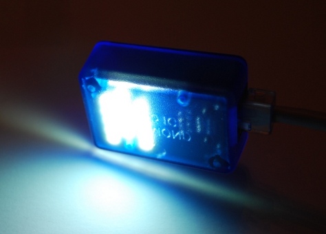
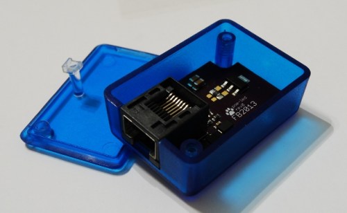
This project is a small PoE flashlight, that can be powered by any 802.3af or 802.3at compliant injector or switch. It can be used as a PoE tester, or if you get trapped in a dark datacenter at night!


TPS2378 PoE Controller
The TPS2378 is a feature rich device, and can be used in different configurations depending on product needs. The typical application (from the device official datasheet) shows the device with some basic external elements, including the circuit for an alternative power source.

The LED application is basically the same, but the alternative power path is omitted, and the APD pin is just connected to RTN to disable the functionality.
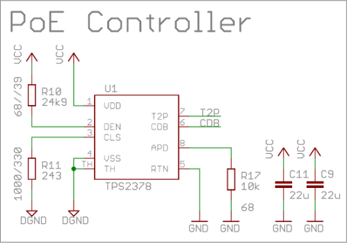
The CDB pin, not used here, is actually very important and should be connected to the enable/slow-start pin of the DC/DC converter in order to make it start only after Cbulk is loaded.
The 802.3at standard specifies some ranges of detection currents to implement the PoE signature, used by the PSE to calculate if a new PD is within its power budget. The detection and signature currents are controlled by the biasing resistors attached to DEN e CLS, and should use the specified value depending on the required class.
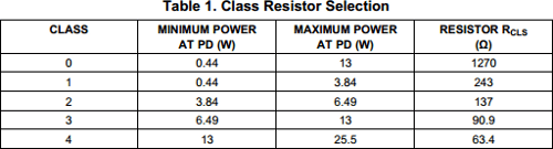
In this case, the load will be at constant current of about 26.7mA, leading to a power of about 1.5W, so the lowest class is selected. It’s important to note that the minimum power is used by the PSE to detect if the load is still present, so that it will be disconnected if it falls below the threshold.

The IC itself comes in a SOIC8 package, with a thermal pad to be connected to VSS to help removing heat from the component when used in high power applications.
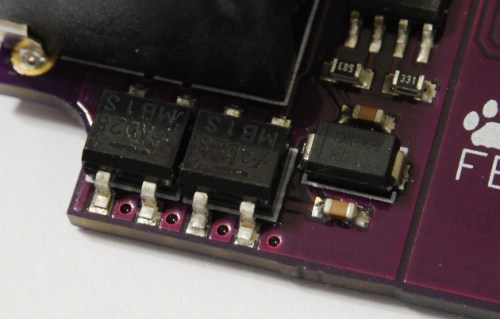
Input
The input stage consits of a pair of integrated full bridge rectifiers, a TVS and some filtering capacitors.
The Ethernet data pairs are not used and shorted together, with an AC termination between one another (which I don’t think it’s really useful but mimics how a normal termination would be).

The bridge rectifiers allow the positive and negative rails to be injected into the circuit in any possible configuration, making the circuit working with power fed both from data and spare pairs, and with crossover cables (which would reverse the voltage otherwise). This is necessary to account for weird installation scenarios, but it also means that the GND voltage is lifted from the PSE one, and it’s one of the reasons why you usually want to isolate the cable power domain from the rest of the circuit.
The diode between the filtering capacitors is actually a Transient Voltage Suppressor (TVS), and it’s used to protect the circuit from voltage spikes induced by the (possibly long) cable on insertion and removal.
LEDs
PoE devices need to draw more than a minimum power all the time to prevent disconnection, and white LEDs make for a really fancy load!
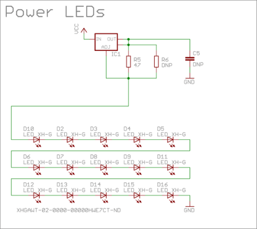
The circuit uses a single high voltage string, made with a series of 15 CREE XH-G high power white LEDs, driven by a single LD1117 in current feedback mode. These are really nice warm white LEDs, and come in a small 3x3mm SMD package. The only downside is that solder paste and hot air is a must to solder this type of LEDs, but the end result is a very professional looking device!


The LD1117 has a maximum Vin of 15V, but in this circuit is not a problem as the device is actually referenced to the LED string input rather than the circuit grounds.
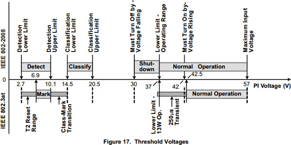
PoE Startup and Signature
When a PoE device is connected, the PD and PSE controllers initiate a signature sequence to recognize each other and validate the power requirements. The actual voltage supplied by the PSE can actually be observed to see the handshake sequence, where every step can be decoded using the threshold recognized by the PD controller, as specified in the TPS2378 datasheet:
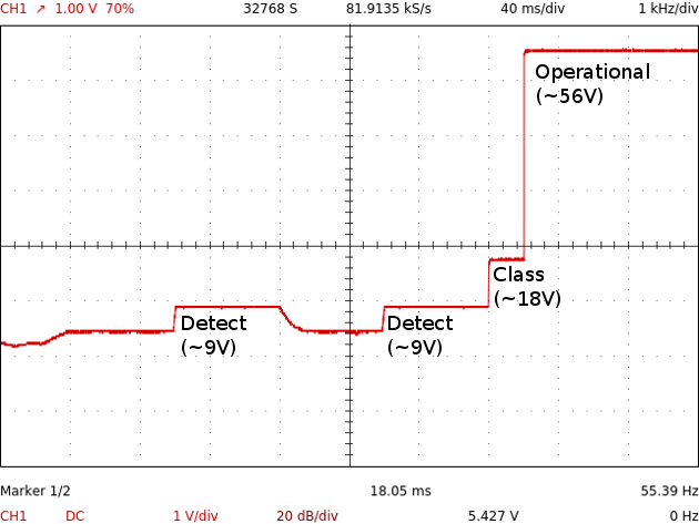
This is an example of a startup sequence, in case of the device is being connected to an 802.3af PSE:
Design Files


All design files are available on GitHub.


Very cool!