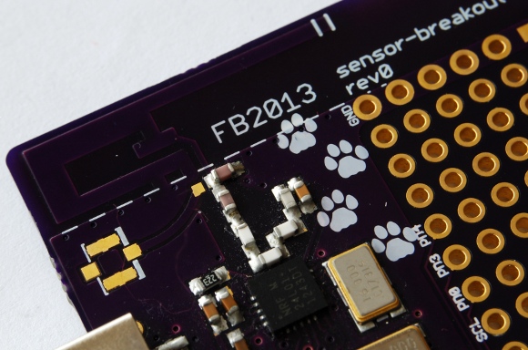
Breakout Board for Wireless Devices Using the Nordic nRF24L01+
2014/06/15 Leave a comment
Recently I’ve been playing a lot with sensors around the house and I’ve decided to make myself a breakout board with all of the common parts the sensor board, including the power supply, microcontroller, wireless interface and
battery charger.


This board can be used to quickly deploy some sensors or actuators, and can be configured to work from battery (for low power applications) or from an USB port (to be used with phone charger). The PCB fits into an Hammond 1551R box.
Microcontroller
The board mounts an ATMega88PA, using the QFN package to keep the space utilization minimal. The footprint is common to many variants of the microcontroller, up to the ATMega328 used in the Arduino.


The AVR is connected to the nRF radio, the standard Atmel ISP programming header and a single LED for status/debug. Two GPIOs are connected to the USB port, and can be used to implement an USB device or a bootloader if a fast enough crystal is used, though I found out that for low power sensors it would be better to just mount an RTC crystal and use the standard ISP or a OTA bootloader for programming.
Radio
The radio link uses an nRF24L01+, a low power 2.4GHz radio from Nordic Semiconductor, commonly found in cordless mice and keyboards, but very well suited to build sensor mashes.

The transceiver uses discrete components to adapt the signal for the PCB antenna, but I plan to replace it with an integrated BALUN in future revisions to save even more space! Also, there is a footprint for an U.FL connector to attach an external antenna.
Power Supply
The board runs from a single 3.3V supply, using a low quiescent current LDO (MIC5301), which can be fed either from a lithium battery (up to 4.2V) or directly from the USB port (5V).
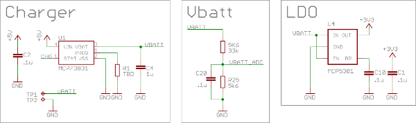
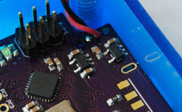

In case of battery operation, the charger is mounted between the USB port (used for charging) and the battery connector. The charger is a Microchip MCP73831).
The USB port also has two mounting options, a Micro-B or a standard A connector. The latter is convenient if the board is intended to be installed directly on a mains connected charger.

Prototype Area
More than half of the PCB is reserved for the actual circuit or sensor, and it’s laid out as prototype area, with a grid of holes at 2.54mm spacing, and some strips of copper at 1.27mm and .6mm for SOIC/SOT/TSSOP footprints and similar.


The first lines of pads are connected to some GPIOs of the micro, plus some ground signals and supply. The two GPIOs usable with the AVR I2C controller have some dedicated off-chip pullups to makes it easier to use I2C sensors.
Firmware
On the project page in GitHub there is some firmware for this board, including an USB bootloader and a basic example firmware to configure the radio and periodically shot some data out of the radio.
Future improvements would be an OTA bootloader, and a basic firmware that uses a low frequency crystal connected to the asynchronous timer for ultra low power consumption in standby with periodic wakeup (current firmware uses the watchdog timer).
Design Files
All design files are available on GitHub.


