USB to 100BASE-FX Optical Fiber Network Card
2013/05/26 26 Comments
Optical fiber is an intriguing technology, deployed all over the world connecting computer networks with the speed of light (well… almost).
Unfortunately, due to the inherent complexity of fiber network installation and management, optical fiber devices have never found their way in the hands of the user, and are usually deployed only by professionals for things such as backbones, long hauls or really fast interconnections.
Luckily enough, older optical fiber Ethernet components, especially 100MBit ones, are now available as a reasonably low price, so I decided to design a couple of USB to 100BASE-FX network cards just for fun and to learn more about working with optical fibers.
This project contains two complete hardware designs for USB to 100BASE-FX network cards, one with a 1×9 transceiver and one with an SFP slot. Both designs are based on the ASIX AX88772B chip, and fit in a compact Hammond 1551 series box.


Also, there are some useful links and information about designing with OF transceivers and SFP modules.
Background
The first thing you may ask is: why would you want to design a silly 100Mbps optical fiber network card when 100BASE-FX is being basically phased-out? (most Fast Ethernet PHYs do not support FX mode anymore) The answer is easy: that’s the best you can design with in-house hobbyst grade tools (read: for fun).
For example, just stepping up to Gigabit Ethernet would require a much more complex design, involving a multi layer PCB with a tuned stackup for controlled impedance balanced lines (LVDS and LVPECL all over the place), and a couple of expensive BGA ICs with all the related availability issues… Not really something you want to use for a DIY project.
Optical Fiber Transceiver
The key component and most expensive part of the circuit is the optical fiber transceiver which, as you’ll see, is a self-contained device on its own, including the necessary circuits to drive the transmission LED or laser, the receiving logic, the actual fiber connector and, if hot-pluggable, an identification EEPROM.
A big issue with optical fiber is that there is no auto-negotiation at all, and there is a relatively high number of standards and proprietary extensions, covering any possible application with many combinations of bandwidth, range, connectors, wavelength, single-mode or multi-mode support, single-fiber options and WDM in general. In short, this means that the two transceivers at the ends of the fiber have to be checked for compatibility: just look at the number of transceivers available from DigiKey to understand the size of the problem.
Luckily enough, at least from a electrical design point of view, things are a bit easier as you mostly need to worry about two things: footprint and electrical signaling.
For the footprint, there are essentially three standards currently in use:
- 1×9 (PTH): that’s the footprint of the oldest (and cheaper) transceivers, it’s relatively bulky, available with both single-mode and multi-mode drivers, and usually comes with an SC-Duplex or SC (for single mode option) connector. That’s what I used in my first design.

- 2×5 (PTH): that’s a modern footprint for fixed transceivers up to multi-gigabit speed. It’s low profile and usually comes with LC-Duplex or MTRJ connectors.
- SFP: this is the current standard for hot pluggable transceivers, with an high speed variant (SFP+) supporting up to 10Gbps. SFP modules always include an identification I2C EEPROM.


All three footprints provide separate power paths for transmitter and receivers, two differential lines and a signal detect line for carrier detection.
As for the electrical levels, every transceiver datasheet specifies one or two possible matching networks, so you should study carefully the datasheets of all the possible transceivers you want to deploy, and implement a compatible version in your schematic.
Luckily enough, the SFP standard covers at least some essential electrical design aspects, such as AC coupling and terminations, but beware of the differences between the “Signal Detect” and “Loss of Signal” definitions: same thing, different polarity!
The differential lines usually carry two PECL or LVPECL pairs, but while the gigabit (and faster) transceivers require a dedicated driver on the PHY, 100Mbps ones are usually connected to the same pins as the standard Fast Ethernet pairs (the one you normally wire to the 1:1 transformer).
Fast Ethernet transceivers supporting FX operations just need to provide the additional “Signal Detect” pin and a configuration bit to disable the scrambler and MLT-3 encoder (only used in wired mode operation).
Sounds complicated? It is, but at least Vitesse was kind enough to design an ultra versatile PHY, the VSC8211, that supports (almost) all of the standards. They also published all of the documentation without NDA, including a great application note that covers many different configurations: SimpliPHY Dual Media Copper/Fiber/SFP.
The only drawback: the VSC8211 only comes in a funky rectangular 10x14mm BGA package… Not exactly well suited to a cheap 2 layer PCB, so let’s just stick to 100BASE-FX for the moment.
USB to Fast Ethernet Controller
Most USB to Ethernet controllers are used for cheap laptop adapters or embedded applications (SMSC ones are quite common on evaluation boards), and do not support FX operation.
The exception here is the AXIS AX88772B, that includes an embedded PHY with FX support enabled by a bit in the configuration EEPROM.

AXIS controllers are notoriously very reliable, and have some properly designed software drivers for most operating systems, especially for the Linux driver that includes EEPROM modification support through standard ethtool commands – and we need that to enable FX mode.
Finally, on the AXIS website you’ll find all the documentation, including the EEPROM layout, register description, and an example schematic and layout with a 1×9 100BASE-FX transceiver.
So far so good, where do we buy the IC from? DigiKey does not list it… Well, the best solution I have come up with, was to buy a couple of USB to Ethernet keys from Olimex and remove the controller and EEPROM using a hot air rework station. Can you do better?
Enabling FX Operation
The AX88772B will run in copper mode by default and to put it into fiber mode you need a configuration EEPROM to modify.
I already had a programmed EEPROM as I desoldered it from a working USB Ethernet key, so the first thing to do is a complete dump to be saved in a safe place, just in case. That’s how you do it (you need to be root, note the interface name is eth1 for me):
# ethtool -e eth1
Offset          Values
------          ------
0x0000          15 5a ec 75 20 12 29 27 00 21 f3 88 72 f0 09 04
0x0010          60 22 71 12 19 0e 3d 04 3d 04 3d 04 3d 04 80 05
...
Here we are interested in the low byte of the “Flag” register, and that’s at offset 0x02. The bit five (1 << 5) is defined in the datasheet as:
EPOM: Embedded PHY copper/fiber Operation Mode
 1: Sets embedded PHY in copper mode (default)
 0: Sets embedded PHY in fiber mode
So we check that we are pointing at the right byte with:
# ethtool -e eth1 offset 2 length 1
Offset          Values
------          ------
0x0002          ec
And finally we change that register to mask out our bit with:
# ethtool -E eth1 magic 0xdeadbeef offset 2 length 1 value 0xcc
If you get no error messages, congratulations! Your AX88772B is now running in FX mode!
The magic number is defined in the kernel driver, and it’s used to ensure that you are pointing to the right device.
Design Issues
The actual schematics for the converter are quite simple and mostly based on the reference design. You may want to keep into account that the optical transceiver uses a significant amount of power to operate (I measured up to ~1.8W from USB in my tests), and a minimum of dissipation area for the regulator is necessary for continuous operation. An even better approach would be to include a proper switching regulator.

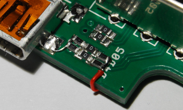
The only issue I have found is figuring out if the polarization network was needed or not for the SFP version. I did not have the datasheet for the transceiver I used, and the one I found on the net had the polarization network inside, so I just left it out of the design.
Turns out I was wrong, but nothing that can’t be fixed with a bit of wire and some resistor.
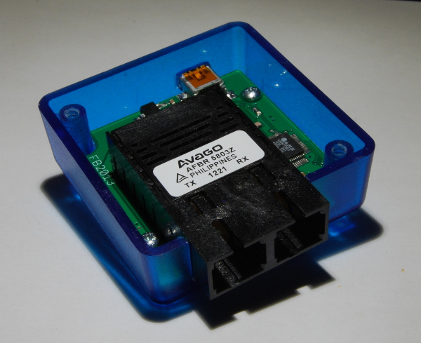
1×9 Version
The first version of this project uses an Avago AFBR-5803Z, and was tested using an old PCnet32+ based network card bought on eBay (which mounted the Agilent component: the HFBR5803).
Here are some pictures of the board, mounted inside of a Hammond 1551R box.


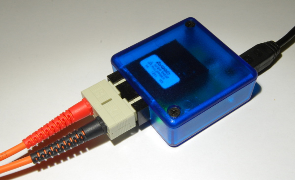
SFP Version
The second version is more interesting, as it’s using an SFP transceiver from River Stone network that I got from eBay for just USD $5!
The SFP cage uses press-fit tabs to lock on the PCB, and that’s great, but I had to modify it a bit to fit in the Hammond 1551H box… the end result is a really compact design.


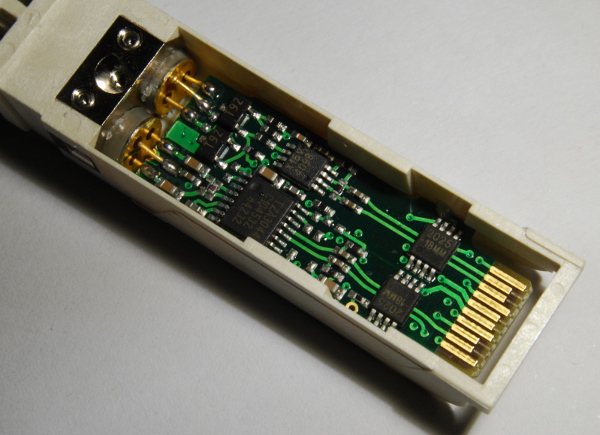
Inside the Transceiver
Curious of what’s inside the transceivers? Me too!
This is a picture of the Avago module:

And this is under the cage of the River Stone SFP module:

Conclusions
That’s it, both designs works fine in the test I made and are up to their specs (100Mbps… I know, not impressive nowadays, but still good!).
Wants to build your own? Grabs my design files from GitHub.

The schematics in PDF version can be downloaded from here for the 1×9 version and SFP version.


Such a neat layout, it’s a pleasure to watch it.
Very interesting the massive decoupling for the ASIX controller, it’s really a struggle to properly decouple when you only have two layers… and 64 0.4mm pitch pins!
How did you manage to desolder and re-solder the ASIX so neat? You really did a nice job with that!
I see a practical use for this interface, apart from the DIY fun: electrical insulation is guaranteed, so it can be ideal to galvanically separate e.g. metering devices, or even audio stuff!
Great job!
Thanks! Desoldering and reflowing was really easy with the hot air and a bit of water soluble flux, it comes out really good.
Electrical insulation is one of the plus of optical fibers, trough I’m not sure this is used for telecommunications, as standard Ethernet is relatively safe as well.
Fabio
Hi,
nice website and interesting design, it’s the first time that met ASIX controllers, I was looking for something similar to cover larger distances with the USB protocol at high speed (480Mbit/s).
But, with this device you convert the USB to a ethernet with fiber interface so you need a PC with a fiber optics ethernet interface, I’m right?
I can’t use two of them as a usb cable extender…
Thank you
ACM
Hi!
The ASIX is really an USB Ethernet interface, so you can’t really use it as a media converter. Beside that, I think that such a think exists, though it may be hard to obtain…
Hi Fabio! avozmozhno you buy 4 of devaysa USB to 100BASE-FX Optical Fiber Network Card, if so, how much will it cost? Nick
Hi Nick!
Unfortunately right now I dont’ have in plan to build more of these and I only built the two prototypes you see in the pictures anyway. If you plan to build some on your own (all the design files are on Github with CC BY-SA license) you can expect this thing to cost about $50 in BOM *alone* for small runs, which is about the price of a commercial 100BASE-FX media converter on Amazon! :-)
Just out of my curiosity, do you have a specific use-case, like on a laptop or something?
Thanks for the interest!
Fabio
Also, consider this an hobby grade design – I would not trust too much this thing to pass a climatic chamber or EMC test…
Hello, Fabio,
Thank You very much for the great article and useful documents!
I have a USB to 100BASE-TX converter at hand which is using ASIX AX88772C.
I am considering to install the modified ASIX driver under Debian Wheezy in order to check whether I could dump/change the data in EEPROM.
According to the manufacturer, the C version should support this.
However, with the stock driver it did not seem to work, so most probably I should install the modified one.
I have yet to figure out whether any special procedure is needed.
Do You happen to have any experience with this particular ASIC?
Thank You very much!
Best regards,
Nickolay
Hi Nickolay! I have no experience with the -C part, but it looks like a pin-to-pin replacement with just the AOAC extension. The register and “PHY operation mode” bit are still there (as most of the other registers I guess), so I would expect this to behave in exactly the same way as the -B part I’ve used.
Not sure what you mean by “modified driver”, I think this should work with the standard mainline driver, but you may have to add the ID for your device if it’s brand new (send a patch!!). The code for changing the eeprom is there (I used a plain driver) so once the device is recognized the instruction on this page should work fine. Feel free to paste here the error you get from ethtool if you have one!
Hi Fabio,
Please, excuse me for the late reply.
Probably the reason for the error I had encountered was because I was using Debian Wheezy and maybe ethtool was not the latest version.
(I will try this again and then copy the error here. It pops when I try to dump the EEPROM with ethtool -e ethx).
I also tried with Debian Jessie/testing and Linux Mint Debian Edition (LMDE).
With either of them I could perform the commands you have listed above.
Here are the dmesg messages from LMDE:
[ 540.700072] usb 8-2: new high-speed USB device number 3 using ehci-pci
[ 540.845010] usb 8-2: New USB device found, idVendor=0b95, idProduct=772b
[ 540.845023] usb 8-2: New USB device strings: Mfr=1, Product=2, SerialNumber=3
[ 540.845029] usb 8-2: Product: AX88772B
[ 540.845034] usb 8-2: Manufacturer: ASIX Elec. Corp.
[ 540.845039] usb 8-2: SerialNumber: 000006
[ 541.221215] asix 8-2:1.0 eth1: register ‘asix’ at usb-0000:00:1d.7-2, ASIX AX88772B USB 2.0 Ethernet, 00:80:8e:8d:8e:93
[ 541.221250] usbcore: registered new interface driver asix
On the chip itself is written ASIX AX88772CLF.
Thank you very much for your support!
Kind regards,
Nickolay
Sweet, so it does look like a -B part on the system… well, feel free to paste the error you get here if you still have problem dumping the eeprom!
Hello Fabio,
a similar commercial product can be found here
http://www.lyconsys.com/index.php/en/products/usbsfpnics
They have also an asix chipset inside. Driver source code for this can be found in the mainstream kernel sources asix.c.
Best regards
Michael
Cute, it’s also using the same Hammond box. :-)
Hello Fabio,
I’m really glad I found your blog :) I was planning to do a similar thing, though I guess I need to improve my soldering skills significantly for these tiny chips. My plan was to make some kind of a diy media converter with either usb, serial or ethernet to fiber conversion. I’d like to go the usb or ethernet way because serial is too slow, something in the 100 mbps region would be nice. I came across some ethernet modules (like the lan8720 http://www.waveshare.com/lan8720-eth-board.htm or dp83848 http://www.waveshare.com/dp83848-ethernet-board.htm from waveshare) and was wondering if I could just connect the pins from the RMII side to the respective pins of the optical transceiver. Well, if it would be so easy probably someone would have done it before. But you seem to have a lot of experience in this field so maybe you could enlighten me a bit if and how my approach would work (or why it would not work).
Best regards,
dodelijk
Hi Dodelijk! RMII is a parallel bidirectional bus with some control logic, and in its basic form only supports connecting a MAC to a PHY. You cannot connect the RMII side of a PHY directly to a fiber transceiver, but with some specialized PHY you can connect two PHYs back-to-back, and configure one of the two into fiber mode (that disables negotiation, scrambling and MLT encoding if I remember correctly) and connect the fiber transceiver instead of the magnetics + copper connector. This is how media converters are done as far as I know.
Back to back PHY connection and fiber transceiver modes has to be explicitly supported by the PHYs, and I don’t think that the two you linked works in that configuration. If you want to do this I would suggest you to look into the Micrel KSZ8041FTL: http://micrel.com/index.php/products/lan-solutions/phys/article/23-ksz8041ftl.html
From the Feature list:
– Fiber support: 100Base-FX (KSZ8041FTL only)
– Back-to-Back mode support for 100Mbps repeater or media converter
Both modes are well explained in the device datasheet (http://micrel.com/_PDF/Ethernet/datasheets/ksz8041tl-ftl-mll.pdf, from page 37) and the design kit includes some option for fiber mode (http://micrel.com/_PDF/Ethernet/hw_designkit/8041TL-FTL/KSZ8041TL-FTL_v1.4_DP.zip). The examples uses a 1×9 transceiver, but you should be able to use a more modern SFP one. Those are available dirt cheap on ebay so you only have to buy the connector and cage.
Best of luck with the project!
Thanks for your reply Fabio! The controllers I mentioned do not support a back-to-back connection. So my idea would not work :( . I took a look at some PCBs of media convertes via the google image search and they seem to use only one controller. So probably similar ones to the micrel chip you mentioned. I also have a media converter which has only one controller (IP113A http://pdf1.alldatasheet.com/datasheet-pdf/view/218725/ETC2/IP113ALF.html).
The easiest solution could be to use the AX88772B chip.
I also have some of those usb to ethernet adapters with this controller and was wondering if I could not use this directly. I switch the controller to fiber mode, plug in an ethernet cable into the rj45 jack, the opposite end of the cable is spliced and e.g. the transmit pins are connected to the respective pins of the optical transceiver. Of course the same would be done with another adapter and the receive pins (from another optical transceiver). The optical transceivers could then be connected through a fiber optic cable.
The main question would be if the optical transceiver could still understand the electrical signal after it went through the lan transformer (and maybe some capacitors and resistors)? Do you have any idea if this could work or what could be done to alter the signal after it leaves the rj45 jack in a way that the optical transceiver can handle it?
I think you could do a single chip media converter with Micrel parts using one of their three-port switch, try to poke around on their website, the part number tables lists fiber capability.
I doubt the idea of keeping the existing jack is going to work, that’s probably going to mess the signal up whenever you switch the controller to fiber mode. That said you can de-solder the existing connector and magnetics and wire the fiber transceiver in, but you also need to wire the necessary biasing resistors (I have that in my schematics for the AX88772B).
When you plan to implement this with an AX88772B chip you should have a look the the Realtek RTL8201CL phy. This phy is very cheap and supports fiber.
Why? The AX88772B has fiber support with the integrated PHY, making this a single-chip solution, that’s why I used the -B version in the first place. You could do the same with a MAC + PHY solution but I would have used a Micrel PHY in that case, since those are available on Digikey on single quantity and the datasheet does not require an NDA. I’m a bit of a Micrel fanboy, I’ve used many of their parts in the past and the documentation is usually of very good quality. :-)
Hi therte, i came across this blog when iam thinking of doing something like, i have SFP 1.2 gbps sfp to fiber transcievers 2 of them.So iam thinking of creating usb 2.0 to SFP to fiber to SFP to usb 2.0.I wan to do it as part of my college project.However iam very confused to use which chip for such conversion process.Could you help me with that please.Here are SFP transcievers i have at hand.
Click to access HFBR-5701LP-Avago-datasheet-7284757.pdf
Hey hi, the electrical interface for gigabit transcievers is different than 100Base-FX ones, when I did this (back in 2013) I could not find any gigabit USB-Ethernet ASIC to do that, the only option I had was some USB ethernet interface with an RGMII port and some unobtainable Vitesse BGA RGMII serdes for the trancseiver. I don’t think the situation is much better now. If I was to do that now I would consider a commercial USB-Gigabit adapter and a gigabit media converter, take them apart and redesign them into one.
hello,
can i know operating voltage of these cpacitors i.e for 1uf,2.2pf and other caps
i have question.After finising this devic, when you plug into laptop will it recognised by laptop without plugging fiber optic cable or do we need to plug in fiber optic cable on other end to be recognised by pc
I need some quick advice.I did same as you.But when i plugged in the usb to sfp converor to laptop,it does not recognise it as any device and does not show in device manager in windows.Can you know what is the problem.
Hello dear Baltieri
I am doing project about USB to Fiber Optics converter. I use IC AX88772BLF and 93c66 EEPROM. Can you please send me EEPROM codes?
Thanks in advance.
Hey there’s no code in the EEPROM, it’s just for configuration stuff, like the USB IDs etc, the controller works just fine without it. Unless you want to make a product and sell it you don’t need to worry about it, if you care, the format of what you need to write in there should be in the datasheet.