AVR Watch
2012/04/01 7 Comments
Following the trend of doing things just-for-fun, this is a wrist watch using an AVR microcontroller and 7-segment display!
Features:
- Open firmware and hardware design files
- AVR and V-USB based
- Uses SMD 7-segment display – retro look!
- Integrated USB Maxim battery charger
- Shows how to scan-drive 7-segment displays without external components
Drawbacks:
- Short battery life (less than one week with a 100mAh LiPo battery)
- Tricky to hand solder (if you don’t have an hot air station)
- Makes people thinks you are crazy (I should put this one on “features”…)
- Looks like a small time-bomb, I would not wear it while in an airport
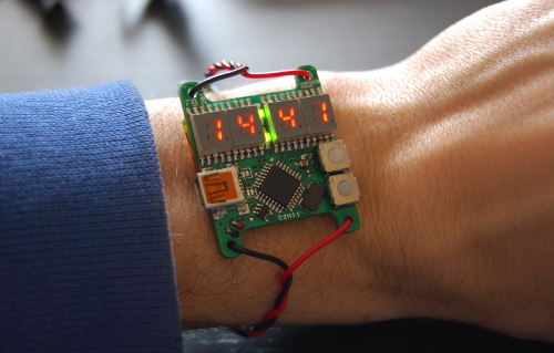
As most of my design, I made this one because I had some 7-segment display laying around and I wanted to build something with those (that’s also why I don’t have a project BOM). Also, I like the idea of having a DIY watch which looks like a lab power supply (it also displays battery level in Volts).
Design Notes
The ATmega168 used in this design have the possibility to use Timer2 in asynchronous mode, usually with an external 32kHz crystal (typical for RTC timers), which allows you to stop all other clocks and obtain a very low power consumption (in the micro-ampere range for the “P” version).
The drawback of this configuration is that it requires a low frequency crystal connected to XTAL pins, so it’s not compatible with requirements of the V-USB soft-USB stack. For this reason, this implementation uses a 12MHz clock and reduce idle power consumption by deactivating the USB and down-clocking the MCU to 3MHz when needed.
An alternative design would be to remove the USB stack, clocking Timer2 from a 32kHz oscillator, and use the UART port for configuration (there are two solder-jumper for connecting the TTL UART to the USB port).

Operation
The firmware is normally in standby state, with the display off and only the timer 1 in RTC configuration and pin-change IRQ activated.
Press the upper button to display the clock for 5 seconds! 7-segment displays takes quite a lot of power so they should stay on only for a short time.
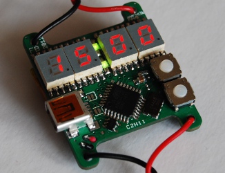
Press the lower button to display the battery level… in volts! In this state you can press the button again to toggle USB connectivity and low power mode (indicated by the 4th display decimal point). USB should be deactivated when not needed, as this engages a /4 clock prescaler thus reducing idle power consumption.

When connected to a PC via the USB port, you can set the time issuing the CUSTOM_RQ_SET_TIME (0x01) request to the control endpoint (yes, you need a PC to set the clock), passing a valid UNIX timestamp in the index/value words. You will find a script to do that with usbtool (from V-USB sources) in the project repository, and it works like this:
#!/bin/sh

time=$( date +%s )
time=$(( $time + 60 * 60 * 2 )) # this is for CEST
time=$( printf %08x $time )

high=${time:4:4}
low=${time:0:4}

usbtool -P AVR-Clock control in vendor device 0x01 0x$high 0x$low
Also, you can send a CUSTOM_RQ_RESET (0xff) request to reset the MCU while pressing the upper button, so that you can jump on the bootloader (bootloadHID) to load a new firmware.
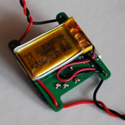
Battery and Charger
To charge the battery, just connect the USB cable. The design uses a MAX1555 LiPo charger in 100mA configuration to charge the battery and lights up the decimal-point in sequence while charging.

Construction
This design uses only SMD components, so it can be quite tricky to assembly if you don’t have an hot-air station. In that case I suggest to mount in the order:
- ICs and oscillator
- Passive components
- USB connector
- The two small LEDs
- 7-Segment displays
- Push buttons
In the source code repository you’ll find a bootloader which have to be programmed one-time. This allows you to hack the main firmware without using an external programmer.
To do the first programming, however, you need to build an ISP cable, and temporarily wire it the ISP test-points (again, you need a steady hand for this).

Good luck with it!
Design Files
As always, you can download the hardware and firmware files for this design from
GitHub.

The schematics in PDF version can be downloaded from here.

The PCB is available on BatchPCB!


This. Is. FREAKIN’. AWESOME.
Guys, I know that dude, he’s really kick-ass, and these are the results! A simple idea, just masterly made real.
I wonder if we’ll ever see a diy kit of this jewel for sale…
Wow… I like the unjustified enthusiasm.
Let me just add some random exclamation marks with some trailing ‘1’… here they comes:
!!!!!!!!!!!!!!!!!!!!!!!!!!!!!!!!!!!!!!!!!!!!1111111111
Thanks! :-)
Eccomi qua Fabio! Ho trovato il tuo blog (sito, direi..)… fantastico! E Pazzesco l’orologio! Ho in mente una serie interminabile di progettini che mi piacerebbe realizzare, ma prima devo prendere confidenza con il mitico BatchPCB e dei programmini utili allo scopo… dovremmo vederci ogni tanto, sai che pazzie verrebbero fuori? :) Intanto complimenti ancora!
Ciao Federico!
Grazie per i commenti. Eagle praticamente si usa da solo e da li a BatchPCB ti basta lo script per generare i gerber ed e’ fatta… tuffatici!
Se ti servono dritte o vuoi farci due chiacchiere scrivimi una mail! Sono sempre dispnibile tempo permettendo.
Salutoni,
Fabio
This is great! But I am curious about how you drive the 4 displays with only 7 pins on the microcontroller. I am very new and thought you would need some shift registers to drive four 7 seg displays. Please let me know how this is done. I would greatly appreciate it.
Hi!
You don’t really need any port expander or shift register to drive the 7 segs, but it takes more then 7 pins.
Specifically, it takes a pin for each segment plus a a common pin for each number (look at the schematics!). Usually you would need an external driving logic for the common anode/cathode pin, but you can just use an AVR pin only in tri-state/drive mode to emulate that. Just keep in mind that the maximum current you can sink into that pin is 40mA.
The actual code is nothing special (it used to be almost a second “hello world” some time ago!), you can find the code in the github repository here: https://github.com/fabiobaltieri/avr-watch/blob/master/firmware/clock.c#L94. That’s basically a timer-tied cycle that lights up all the digits one at a time, if you slow down the timer you can see the actual refresh rate. Just browse through the code!
Cheers,
Fabio
Thank you for the response. All is clear now.