DIY Cheap Internal WiFi Antenna
2012/06/02 14 Comments
Some time ago I put my hand on a couple of broken Axis network cameras which were about to be trashed. These cute small devices have an image sensor with a plastic lens, a wired and a WiFi interface to connect to an external network, and many other nasty features.
The cameras had a busted Marvell power supply, which probably broke ahead of time because of the high working temperature, and once replaced with an LD1117 (I know, not the best of choices…) they were as good as new.
The one thing I did not like about these cameras was the cheap WiFi antenna, which is mounted far away from the casing and gives an old bulky feeling to the device.

This post is a tutorial on how to build an internal WiFi antenna to modify this kind of devices!
The Device
My camera is an Axis-207W, but this internal antenna should work with any plastic-cased device.
The important thing is to identify the connector, if any, used on the WiFi interface. The most common thing to find here is either a directly-soldered coax wire, or an U.FL connector.
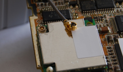
To build the antenna, you may either find a pigtail with the correct connector to cut out, or just recycle the current cable.
Antenna Design
The antenna design used is from a paper from jpier.org, which is really nice because works both in the 2.4Ghz and 5Ghz range, and because is planar and easy to build.

You can find the PDF printout file with the mirrored layout here.


Construction
The easiest way to mass produce this kind of antenna is to make a laser cut out of it using a metal plate of copper-nickel-zinc alloy (see chapter 2 of the design paper), but if you want to just build out a couple of samples you can do that manually with just a printer, some copper tape, and a cutter.
This is the procedure:
Print the shape of the antenna (mirrored) on a paper, and stick the back of the shape with a strip of copper.

Cut out the shape as precise as you can using the cutter and remove the excess pieces.

Optionally, stick some double sided tape on the back of the antenna (the printed side), to give some strength to the shape, and to fix it to the device case later on.

Solder the antenna cable tip and sleeve to the appropriate points of the antenna.

Stick the new antenna to the device and wire it up!

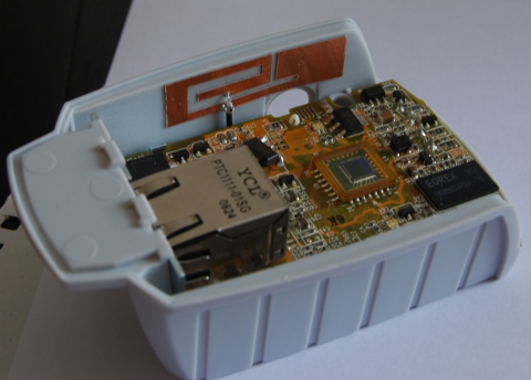
Also, tap the hole of the old antenna.

Performances
If properly mounted, this design gives performance similar to the standard dipole.
When choosing where to mount the antenna on your modded devices, try to mount it vertically (to get the best radiation pattern), with a short cable but as far as possible from metallic part of the chassis and the PCB of the device.
You can use this antenna to modify any WiFi device, including router and access points, but althrough I found it to be very good performing, try to always do your own tests before permanently remove the old antenna.
Thanks to C.-T. Lee, S.-W. Su, and F.-S. Chang for the antenna design, my girlfriend Maria for the pictures and Rudi for the cameras!
Happy modding!


What’s the range for this antenna? I’m thinking of using this in a tablet I have that has poor wifi reception.
In the paper it says that the inner cable must be connected to point A and the outer shielding must be soldered to point B.
Does it matter if the solder connects point A and B (shorting the circuit)?
Because that’s a very small space to solder in.
Hi Bob,
the design seems to have performances just slightly inferior than a normal dipole… give it a shot! Just try to not break anything in case you find out that it’s not an antenna related problem
Anyway, you should really connect the coaxial cable as indicated to get it working, and try to put it as far as possible from metallic parts.
Oh – by the way – I’m not an antenna expert, these are just generic tips when working with radio devices… try to experiment if you feel it!
“…as far as possible from metallic parts.”
Would the aluminium housing of the tablet have any influence? That would be a bummer :(
I also found this site http://www.antenna-theory.com/basics/main.html
So much new stuff to learn and experiment with :)
I think that any electrical conductor would disturb the antenna tuning in some way or another. Take a look at ipad teardowns, you’ll see that the antennas are either behind the plastic apple logo, or near the front bezel – the 4g version should also have some plastic element in the casing.
Thanks for the link, have fun with your tests!
Pingback: Making Time Lapse Video with IP Cameras « fabiobaltieri
– Supposedly, the cable braid shield is also soldered to the coppper plate but at the outer point?
– And what if no connector at the WiFi adapter’s end? One needs to find then grounding for the braid shield of the cable?
(Sorry, no antenna expert)
Well, I suppose that every change in the feed and return point connection will change the antenna characteristics and should be avoided.
If the adapter does not have a connector you should find the feed and a good ground connection for the braid and you may also want to isolate the feed trace from an internal antenna if present.
Sorry again as unclear, is the braid shield also soldered to the copper plate antenna in your solution? Can’t see well in the photo. Got the adapter part though. Thanks.
Yes the braid is soldered to copper plate too, if you check the original design file (linked in the article) the point is indicated more clearly than in my picture! (didn’t have a macro lens back at the time… :-)
Can we use a glass epoxy pcb for design the antenna?
Hi! Again, I’m not an expert on the subject so I can’t say for sure, but intuitively I think that if you have the tools to re-tune the antenna it may work fine, unless you’re changing fundamental design aspects, like feeding the antenna from a microstrip instead of a coax cable, or placing the antenna near a ground plane.
It possible to use this DIY Antenna also for GPS or 3G network?
Thanks for your reply.
Francesco
Hi! Nope, this would only work for 2.4GHz or 5GHz based radios. You should look for some design that works at the proper frequencies.
“Great DIY WiFi antenna idea! Improving your WiFi signal without breaking the bank is always a win. Your post offers a simple and cost-effective solution for those looking to boost their internal WiFi performance. Thanks for sharing this handy tip!”