LNA for RTL Based SDR Receivers
2014/06/22 46 Comments
SDR is one of the trendy technologies of the moment, and I couldn’t resist the temptation to buy one of those cheap RTL2832U based DTV receivers, usable out-of the box as a SDR.
The device comes with a fronted (R820T) with a built-in LNA, which is normally powerful enough to fed the receiver when using a short cable, but since I wanted to experiment with an antenna mounted on a relatively long and thin cable, I built a small LNA to be mounted at the far end, near the antenna.
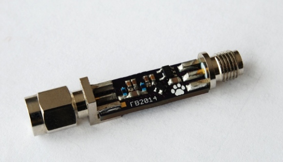
The LNA is based on the Mini Circuits PSA4-5043+, and the board is designed to be as small as possible to fit in line with the antenna and cable, and to be powered by the receiver itself.
PSA4-5043+
The Mini Circuits PSA4-5043+ is an LNA used in many designs for SDR antennas, including LNA4ALL and F5ANN’s ADS-B Active Antenna.
The device operates up to 4GHz, and it’s powered by biasing the output pin to DC, usually from 3V to 5V. The power can be provided from a dedicated supply or from the antenna cable itself, which is preferable if you want to mount the LNA near the antenna. The cable is normally biased using a dedicated bias-tee circuit (see F5ANN page), but as I did not want more cables and devices, apart from the receiver, I decided to modify the receiver itself to bias the signal instead.
The LNA
The LNA circuit is very simple, and it only includes connectors, some passive to extract power and bias the amplifier, a linear regulator and the amplifier itself.


The two signal inductors are used to filter the DC power from the cable (L2), feed it to the linear regulator (not shown here) and feed a regulated DC (L1) back into the amplifier (U1). Optionally a third inductor may be connected from VIN to the antenna connector (after C3) to feed a DC supply back on the input cable, allowing for connection of multiple amplifiers in series.
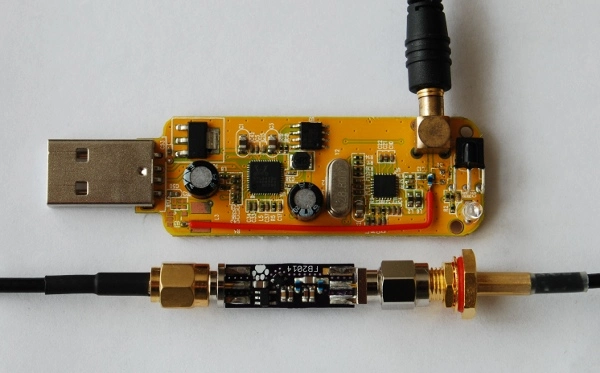
Radio Modifications
To supply power to the cable, rather than using an additional external device, you can easily modify the receiver and add a biasing circuit.

The modification involves first verifying the existing circuit to ensure that the input is already DC filtered (the series capactior C13), then removing any existing clamping protection that would short the DC to ground (D8 in the picture) and finally mounting a inductor from the USB 5V supply to the output line.

The modification allows to operate an active antenna without external components, but be sure not to connect any passive antenna shorted to ground, as that would quickly destroy the biasing inductor in the radio since there is no current limitation circuit (that’s why my board looks so bad around the missing protection diode :-).
Performances
This a screenshot from a test on the radio with a short cable (blue), with a long cable (purple), and with the long cable (about 10m of RG174, a very lossy cable normally not used for long runs) plus the LNA (red line).

The results are quite good and show that the LNA is powerful enough to compensate for the loss for a cable of that length (about 20dB at 400MHz).
Design Files
All design files are available on GitHub.


Pingback: New Inline Low Noise Amplifier Design for the RTL-SDR and RTL-SDR Power Injector Modification - rtl-sdr.com
Wow, awesome! Thx 4 sharing this one.
Looks great – many thanks for sharing!
You might also mention that this circuit does not only compensate for the loss, it also lowers the noise on the front end significantly – resulting in a better S/N than before! I operate a similar amp with a TV signal splitter behind it and run several SDRs on the same antenna – the amps gain gets reduced by the splitter so that I have no loss on the end, just a better S/N on each receiver!
Best regards
Joerg
Hi Joerg,
that’s true, I did not really do an in depth analysis on the SNR difference compared to the integrated front-end with a total equivalent gain, and from what I’ve seen it also depends on the signal frequency (and possibly something else)… That said the example I’ve posted shows what you described… it may deserve some better benchmark! :-)
Thanks for the comment, post a link to your setup if you have it published!
Fabio
Hi,
I couldn’t find the mcp5301 ldo datasheet, can you upload the specs or better a bill of materials / material list for the components as well ?
Thanks
Hi! My bad, wrong part number in the schematic, I’ve put it wrong in one and keep bragging the wrong symbol around.
The correct P/N for the LDO I’ve used is MIC5301, but you can really put any LDO with that pinout (it’s quite common) there, the complete part number is MIC5301-3.3YD5. I uploaded a corrected version, thanks for pointing it out!
Hello.
you’re selling wired and tested this product?
Hi! Nope, sorry, I don’t have plans for selling this. I would suggest you looking into the lna4all, which is basically the same but does not come with the phantom power inductor mounted. Sorry!
Cool. Thanks for sharing the design.
Did you use 0805 for C3 & C6 on the board shown? Is it ok to use the 0603 for these components?
Nice spotting that! :-) That’s because it’s just what I had available when I assembled it, the footprint is actually for a 0603 but the components fits anyway.
I am going to try building some of your boards, and have received the PSA4-5043+. Man are they small. I hope I didn’t get the wrong parts. :-)
Yeah, my picture makes it look huge, don’t sneeze on those! (I’ve actually lost some tiny balun by doing that :-))
Have you decided to sell these yet ?
Hi! Nope, no plans for that.
Hi Fabio,
What kind of inductor are you using on the dongle, and for L1/L2? What is its highest frequency?
Regards, Paul Boven.
Hi Paul, the one I’m using is a LQW18ANR22J00 (all three of them), it should work fine up to 1.2GHz, which is more or less the frequency range I wanted to use this for. If you pick a different part number you can build a version that covers the full rtl-sdr span.
Hello, which part would cover the whole range? ~56-2100.
Well it’s hard to cover a range that wide with a simple design. Some guideline here: http://en.wikipedia.org/wiki/Bias_tee, basically you want high inductance for low frequencies, and high resonant frequencies for the top end. The numbers are in the datasheet.
Hi Fabio, thanks for sahre it.
Where to buy PSA4-5403? preferable in Europe…
Regards,
Hi Carlos, it seems like major distributors don’t stock Mini Circuit parts… eBay is what works for me for those, maybe you can get some parts directly from them as well if you work for design house or something.
Hi Fabio, very nice job… I like it!
do you have a couple of PCB (only) for sale? I already have all components…….
Hey Roby, I shared the project on OSH Park, you should be able to order it directly from them at https://oshpark.com/shared_projects/KV2mfWeS.
Thanks a lot
Roberto
Hi Fabio
Do I need to add a BAV-99 to the input to protect the LNA from Lightning storms and static if this is used outdoors?
Thanks
Hi, that would work for static discharge protection (similarly to the one already present on the rtl-sdr card), but don’t count on it for stopping lightnings, that’s what Lightning rods are for… :-)
Would I need to redesign the PCB or do you think I would be able to find space to place one at the input of the LNA?
You can certainly hack it together but if you have the chance to redesign the PCB you should definitely do it.
Brilliant design, if someone does a board redesign for the BAV99, could they also extend to slightly to replace C6 by A capacitor (C6) a SAW filter (eg TE-1090EC) another capacitor (C6 again)
Thanks Peter! Yeah that would be cool, actually when I designed this I wanted to have a footprint for a SAW filter as well but I could not find anything interesting on DigiKey so I’ve just left it out. Feel free to post a link if you publish something!
Your micro phantom power lna looks awesome, I know you do not sell the unit, but any chance the board is available? Thanks Dan KY4JLY.
Hey Dan, sure thing, you can get it from oshpark at https://oshpark.com/shared_projects/KV2mfWeS.
Hi Fabio,
I am trying to build the LNA but I have problems picking the inductors and the LDO. I can not find locally the ones you used and the choises I have are no match to yours. Could you please have a look and suggest one from here? http://www.tme.eu/en/katalog/#search=cw0603&s_field=accuracy&s_order=DESC&id_category=112358&page=1%2C20 .
As the LDO I want to use the
Voltage stabiliser; LDO, fixed; 3.3V; 0.15A; SOT23-5; SMD
Producer: TEXAS INSTRUMENTS
Manufacturer part number: TPS73133DBVT as it has the lowest dropout from them all.
What software/hardware have you used for the Perfomance image?
Thank you.
Hi Dan, the LDO you linked should work fine. For the inductors something that resonates over the frequency you want should be fine, say the CW0603-120 from the list you linked, it resonates at 1.3GHz, and should be fine if you want the LNA for sub gigahertz stuff.
Hi Fabio,
Thank you for the answer. What frequency range do you think we can get with the CW0603-120 inductor? Are we looking at 100MHz – 1.3GHz range or is it something else? I am aiming to get the 119.19MHz voice from airport TWR and also to get the ADS-B for planes location data which is 1090MHz. In our case inductor the max freq. of operation for the LNA is 1.3GHz or is it lower or is it centered at 1.3GHz?
I am sorry to bother you but I am not good at this kind of calculations.
Thank you.
As far as I understand the tee is going to work below the self-resonating frequency on the inductor but I would not know how to estimate how much below that (and I don’t have gears to test that). In my case the one I’ve used (LQW18ANR22G00D) resonates at 1.2GHz, and it seem to have worked fine both at 1.09GHz and at 400MHz. Ideally you would put a test signal into the whole circuit and check the performance of the whole thing on a spectrum analyzer… if you have such a setup it would be easy to try different p/n and see the result, but this is what worked for me in the limit of what I have available.
Oh, hw/sw used… That’s kindof my problem… I currently don’t have access to any RF test gear. :-( The only tests I did were with the rtl-sdr key and some know(-ish) signal.
Hi Fabio
I ordered the components (took many coils to test with). One more question though … do you recomand any setup for testing? I mean a procedure to see the range where the LNA is good? I plan to make 5 of them on home made pcbs with different inductors and check various signals I can find in the air and maybe get a chart with best range. Do you think this will work? Do you know of any software that would help with this because I only know SDRsharp and I don’t think results will be very accurate?
Thanx
Well yeah ideally I would suggest you to get a vector network analyzer and do a full characterization of the device. That’s probably over budget though (guessing…) so – yeah – what I did and what you can do is to do a comparison testing on “known” signal using the rtl-sdr dongle to see if the results are what you expect.
Will this work? Kindof, what you see is what you get, unless you get proper test equipment it’s tough to do a proper measurement and troubleshooting – and RF gear does not come cheap.
SDRsharp or any rtl-sdr based FFT tool is equivalent for this, the performance is limited by the dongle anyway, and it’s enough to do a “rough” testing. I used the osmocom_fft because it already have some spectrum hold function, which works reasonably well for A-B comparison.
What is the use of 1pF capacitor C9? I notice it is disconnected in your picture.
Hey Bill, I’ve seen similar projects using a cap in that position for some sort of tuning/filtering, so I’ve put one as well but never used it.
Thanks for sharing the info. When ordering some other PCB from OSH Park, I saw your ADF4351 synthesizer board. It looked interesting for ham projects so I ordered 3. Do you have a schematic/writeup for that one?
Hey Bob, unfortunately I’m a bit short of time for writing articles up recently, though I was hoping on writing something for that one. The board works great if you need test signals. If you want to try it the repository is at https://github.com/fabiobaltieri/rf-synthesizer. It has schematics (eagle), a bootloader, the main firmware and a commandline utility to control the chip via USB, with the math for setting the register from the official kernel.org driver. If you manage to build and flash it the tool is pretty much self explanatory, see the inline help in https://github.com/fabiobaltieri/rf-synthesizer/blob/master/commandline/main.c#L21.
Hey thanks for the comment, love to see that people are interested. Maybe it will help motivating me to go back writing something about this. :-)
Fabio, thanks much for posting the schematic and code. For me, at least, these are all I should need. I need to order parts and all that, but will report back with results as I can. The synthesizers are getting very sophisticated and complete. The 4351 is a good example of this. Thanks, again. Bob
Sweet! Yeah highly integrated components like that are great to get you going even if you don’t have the gear to test a custom RF design. Let me know if it works for you! The board is pretty dense but apart form that it’s essentially a USB-to-SPI thingy. Let me know if it works for you! :-)
Would it work to drop the re-biasing section and regulator, and simply provide DC-IN from the far end of the line? How clean of power does the LNA need?
It would likely work without the regulator, you still need to provide the decoupling and filtering tough. No idea about noise from the power rail, maybe the datasheet mention something? The LDO and decoupling caps (small+big cap) seems to be the rule of thumb here…