Hacking into a Vehicle CAN bus (Toyothack and SocketCAN)
2013/07/23 113 Comments
CAN bus is an automation fieldbus commonly used in the automotive industry as the main network bus to allow communications between the many on-board ECUs on modern vehicles.
The Linux kernel has native CAN bus support at network layer since some years, with a lot of drivers for both embedded and USB CAN bus controllers, so it’s now fairly easy to add a CAN bus interface to any Linux laptop and have a playaround with it.
In this post I’ll show how to tap into a modern car local bus, dump a bunch of data and analyze the trace offline to write a decoder from scratch using the SocketCAN APIs and utilities.
This is based on my experiences hacking into my Toyota… Toyothack!

CAN bus Network Model
If you are new to field busses, CAN bus may appear weird at first sight. The bus is physically deployed as a terminated differential twisted pair with a ground reference, and it’s usually in a trunk-drop topology, where many nodes are connected to a main trunk cable with short drop lines, sometimes using T junctions. The bus runs up to 1Mbps, and the speed directly influences the max bus length.
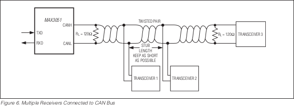
(Image from Maxim MAX3051 datasheet)
What is really interesting about CAN bus is the actual usage model: each packet has single address of either 11 or 29 bits (the latter is called extended frame), and a maximum payload of 8 bytes. The unusual thing is that we think of frame address, not source or destination address, in fact CAN bus nodes does not have an address at all!

(Image from Analog Devices AN-1123 Application Note datasheet)
The idea behind this is that address are used to identify the type of frame (i.e. what’s the meaning of the payload), and all nodes on the bus can send and receive any type of frame. As the bus can have a lot of traffic on it, but most nodes only care about some specific frame IDs and does not have the computational resources to handle the full traffic, each CAN bus controller implements some sort of “acceptance filter”, which is usually a bitmask to decide which range of frame addresses should be received by the node, while all the others are discarded silently.
What this means that while the bus is physically a broadcast (all the nodes are connected to the same cable), the protocol makes it work logically as multicast.
This makes the bus very well suitable in automotive and automation environment, where some sensor may put data on the bus that is used by many processors or actuators, and allows to mix nodes with different computing power on the same bus.
At the same time, nothing prohibit the designer to assign some frame addresses for a logically point-to-point communication between two specific nodes, and implement a stream protocol no top of it: in fact that’s what is done in the standard ISO-TP protocol, and there even is a SocketCAN example application to run a full Linux netdevice on top of it.
One additional feature is that the bus is designed so that lower frame addresses have an higher priority when contending for the bus. This should be kept into account when designing the high level protocol, where often the address is segmented into fields, dedicating an higher portion as a “priority” indication.
CAN bus in Automotive
CAN bus was designed for the automotive environment, and that’s where it’s still widely deployed. A modern car have many different ECUs and sensors, and the multicast nature of CAN bus makes it ideal to distribute the data as needed.
Let’s take vehicle speed as an example, it is transmitted just once on the bus by some wheel sensor, and may be used at the same time by the dashboard, ABS, cruise control, radio/navigation and other devices.
Of course, some data and some nodes are more important than the others, and while CAN bus controller implements some safety features such as error counters to self-disconnect from the bus in case of errors, the bus itself can still suffer from a catastrophic failure, such as a cable short or a cut in the middle.
For this reason, complex cars usually have more than one bus, often running at different speed. As an example that I found on a FIAT car, one bus is running at a relatively high speed (500kbps) and it’s wired only on the front of the car connecting critical systems, such as engine control, ABS, power steering and so on. An additional bus runs at a much lower speed (50kbps), allowing for longer connection segments, and it’s only used by the non critical equipments, such as dashboard, stereo, electric windows, lights, parking sensors etc. This one is also wired into the CAN pair of the OBD diagnostic connector, making this easier to tap into.
All vehicle busses are usually connected to a common ECU at some point, which may be used as a proxy to selectively transport some information between busses, while keeping the physical isolation for safety reasons.
How the bus is laid out is specific to each car, so you may want to search for the service manual of a specific model, where you can usually found information on the physical bus topology. Some really complex installation may also spot additional LIN busses behind CAN bus nodes… Do your own research!
On-Board What??
OBD, or On-board Diagnostics, is a set of standards to provide diagnosis and error reporting from the vehicle ECU.
The idea behind OBD is that as modern vehicles rely heavily on electronics and have a many self test capability, a common protocol should allow a service center to read some standard error code to help troubleshooting. Once an ECU detect some sensor value is out of a “safe” range, the system can store an error code and alert the driver by lighting up the well known “check engine” yellow light. At this point, a service center should be able to connect a generic scanner to the vehicle standard OBD port, and that should give a indication of what have failed in the vehicle history.
How’s that related to CAN bus? The OBD was originally implemented through some simple vendor-specific protocol, at the point that when the standard OBD-II connector was defined many different busses, including CAN bus, were supported on the same cable, and a generic scanner needed to support all of those and guess which one is used on a specific vehicle (see ELM327).
Luckily enough, vehicle regulations become more specific over time, to the point that since 2008, all car sold in the USA are required to implement OBD-II in the CAN bus signaling variant.
This means that in most (possibly all) modern cars, you can find a standard diagnostic connector accessible somewhere near the dashboard, and on this connector you are sure to get access to one of the vehicle CAN bus.
So, what can you expect to find once you tap into that bus with your CAN bus interface? You can’t tell until you try, because apart from OBD data (which doesn’t send anything on it’s own anyway), the bus can be used by the vendor for anything else: it may be the only bus of the car – in which case you get lots of data – or it may be dedicated for diagnosis, and in this case you get nothing at all.
If you are reading this just to have some fun and learn more about your car digital guts, you’ll not find OBD data that interesting, as that’s mostly diagnostic stuff. On the other side, if you manage to attach and configure your interface correctly, turn on the ignition and see a flow of data, that means the bus you’re on is also shared with other vehicle ECUs, and that’s where the fun begins!
So, to sum up: most modern car have many digital busses, and at least one is a CAN bus and exposed on the standard diagnostics connector. You can attach a generic interface on it and send access generic OBD data, but if the vendor decided to use that bus for something else, you’ll also find a stream of vendor-specific frames, with real time sensor and control information, waiting to be reverse engineered.
SocketCAN
On a CAN bus system you have a lot of self-contained microcontroller/DSP based units connected together, each one with its own acceptance filter and possibly injecting some information on the bus, but how does it step-up to be used on a complex operating system? Enter SocketCAN.
SocketCAN is CAN bus stack for the Linux kernel, contributed by a team at Volkswagen Research (well done VW!), and it’s really ingenious in that it implements CAN bus as a network device, exploiting many existing features of the Linux network stack.
What this means practically is that you are going to see your CAN bus controller as a network device, controlled by the “ip” system command.
That’s an example of how a CAN bus device appears on the system:
# ip link show dev can0
9: can0: <NOARP,UP,LOWER_UP> mtu 16 qdisc noqueue state UNKNOWN mode DEFAULT
    link/can
From an application point-of-view this great news, as it means that CAN bus is handled by the well know Berkley sockets APIs and you have full software portability: there is no API difference between an USB interface connected to a big workstation or a memory mapped interface on a small ARM SoC. The main “trick” is that when using a socketcan interface, the application actually send and receive a specific can_frame structure, defined as:
#define CAN_EFF_FLAG 0x80000000U /* EFF/SFF is set in the MSB */
#define CAN_RTR_FLAG 0x40000000U /* remote transmission request */
#define CAN_ERR_FLAG 0x20000000U /* error message frame */

typedef __u32 canid_t;

#define CAN_MAX_DLC 9
#define CAN_MAX_DLEN 8

struct can_frame {
        canid_t can_id;  /* 32 bit CAN_ID + EFF/RTR/ERR flags */
        __u8    can_dlc; /* frame payload length in byte (0 .. CAN_MAX_DLEN) */
        __u8    data[CAN_MAX_DLEN] __attribute__aligned(8);
};
At system level, it means that your applications behave like nodes on the bus: they can be attached to a “virtual” interface and exchange frames with any other node, without knowing if those are real devices on an external bus or other applications running locally on the same virtual interface.
At a low level, this also means that the interface driver is running with fully open acceptance filter, so the kernel actually receives all the bus data and decides whether or not to send frames to any application depending a higher level software filter, but that’s usually not a problem as modern Linux enabled SoCs are powerful enough to handle the full traffic anyway.
At this point you may be interested into how to find a list of supported USB-to-CANBUS devices to play with, and that’s quite easy as all of those are in a dedicated directory in the kernel sources. Either way, this is a quick list:
- ems_usb.c: CPC-USB/ARM7 from EMS
- esd_usb2.c: CAN-USB/2 and CAN-USB/Micro from ESD
- kvaser_usb.c: CAN/USB from Kvaser
- pcan_usb: PCAN-USB from PEAK System
- usb_8dev.c: USB2CAN from 8 devices
Of all of this, I’ve only had experiences the EMS one, but that’s quite expensive and maybe harder to obtain, so the one I would buy right now is the USB2CAN from 8 devices: it’s cheap, you can get one from the webstore and they provide full schematics and firmware upgrades. There is also a repository with the actual device source code, but that’s hardly of any use without the correct programming environment.
As for my setup, I’m using my own open hardware USB AVR + MCP2515 interface. You can find the repository for my design here, but the performances are not that good above 250kbps, so I’m planning a complete redesign in the future.
What if I’m Stuck on Windows?
While I don’t usually consider this case, I’ve seen CANviaUSB used in the development on a critical project and seems to be a great tool. So, if you really can’t avoid Windows, CANviaUSB is probably the free tool for you (the homepage contains a list of supported device).
Hacking Into the Bus
If you’ve read all the way through here I hope you’ve understood that you will have no idea of what’s attached to the bus until you’ve analyzed it. This also means that you don’t know what can break once you start poking on it, so this may be a good time for a bit of a disclaimer:
|
You shouldn’t mess with your vehicle bus while it’s moving unless you are 100% sure of what’s going on. The chance of breaking something critical is high and you can hurt someone (possibly yourself) if you mess up. |
The first thing you need other than a laptop and the CAN bus interface is a matching cable for the OBD-II port. I have an OBD to DE-9 cable from SparkFun, but you may also find a suitable one from your CAN bus interface vendor. As with my interface I used a custom 8P8C based connector, I’ve actually cut my DE-9 side of the cable and crimped the wires to a standard Ethernet Jack.

(Image from Sparkfun)
You should check the cable and interface pinout twice before attaching to the vehicle, as there are many signals on the connector, including a +12V and possibly some vendor specific ones.

(Image from Wikipedia)
– pin 4: chassis ground
– pin 5: signal ground
– pin 6: CANH
– pin 14: CANL
– pin 16: Battery Voltage
This is the actual connector pinout. Be sure to connect the CANH, CANL and GND signals. Shielding and +12V may be useful too but the other lines should be left unconnected.
Next, you should find the connector in the vehicle. The shape is easy to spot but it may actually be hidden under the dashboard, in an internal fuse box or under the ashtray or some other removable feature.
Don’t force the connector too much, many of those cheap cables are badly designed and fits too tight, I actually had to chop off some plastic from mine.
Also, make sure to connect the car while the ignition is OFF for thirty seconds or so – I found my car transmits data for some time even when everything should be shut off.
Device Configuration and Dumpting the Stream
Time to dump some data, but the interface have to be configured first!
The standard command to configure a CAN bus interface is ip, as in:
# ip link set can0 type can help
Usage: ip link set DEVICE type can
        [ bitrate BITRATE [ sample-point SAMPLE-POINT] ] |
        [ tq TQ prop-seg PROP_SEG phase-seg1 PHASE-SEG1
          phase-seg2 PHASE-SEG2 [ sjw SJW ] ]

        [ loopback { on | off } ]
        [ listen-only { on | off } ]
        [ triple-sampling { on | off } ]
        [ one-shot { on | off } ]
        [ berr-reporting { on | off } ]

        [ restart-ms TIME-MS ]
        [ restart ]

        Where: BITRATE       := { 1..1000000 }
               SAMPLE-POINT  := { 0.000..0.999 }
               TQ            := { NUMBER }
               PROP-SEG      := { 1..8 }
               PHASE-SEG1    := { 1..8 }
               PHASE-SEG2    := { 1..8 }
               SJW           := { 1..4 }
               RESTART-MS    := { 0 | NUMBER }
Here you need to set the bitrate to match the one used in your target bus. As you probably don’t know that before starting, you have to take a guess (or probe it with an oscilloscope).
As CAN bus sends error frames if misconfigured, you most likely want to keep the interface in listen-only mode for all the time, so that other nodes does not notice that something weird is happening. Just as you know, what may happen if you forget to do so is that something on the bus notices the problem and either display (like in the car stereo) or records the error.
This is how you set the can0 interface at 500kbps in listen only mode:
# ip link set can0 type can bitrate 500000 listen-only on
If there are no errors you can now bring the interface up and start dumping frames:
# ip link set can0 up
# candump -cae can0,0:0,#FFFFFFFF
At this point, you are receiving everything that is happening on the bus, including errors. You should try doing something on the car, like closing a door or turning on the ignition.
If your bitrate is wrong, you should receive a stream of errors from the CAN bus interface:
$ candump -cae can0,0:0,#FFFFFFFF
  can0  20000008  [8] 00 00 04 00 00 00 00 00   ERRORFRAME
        protocol-violation{{bit-stuffing-error}{}}
...
In this case, bring the interface back down, and try with a different bit-rate. Most common ones are 500kbps, 250kbps and 50kbps.
If you are lucky, you’ll eventually find the correct configuration, and get a lot of valid frames from candump:
balto@balto:~$ candump -cae any,0:0,#FFFFFFFF
  can0  440  [8] 40 00 80 00 00 00 00 00   '@.......'
  can0  442  [8] 42 00 80 00 00 00 00 00   'B.......'
  can0  440  [8] 40 01 80 00 00 00 00 00   '@.......'
  can0  620  [8] 10 80 00 00 00 40 00 80   '.....@..'
  can0  442  [8] 42 01 80 00 00 00 00 00   'B.......'
  can0  440  [8] 42 02 00 00 00 00 00 00   'B.......'
  can0  442  [8] 40 02 00 00 00 00 00 00   '@.......'
  can0  440  [8] 42 02 00 00 00 00 00 00   'B.......'
  can0  620  [8] 10 00 00 00 00 40 00 80   '.....@..'
  can0  442  [8] 40 02 00 00 00 00 00 00   '@.......'
...
Now that you have the data, this probably looks like noise to you, as that’s all part of proprietary protocols used by your vehicle ECUs. If you plan to do some reverse engineering on it, the best thing to do is to record all the data for offline playback, but also to setup a camera in the car to record what’s happening on the dashboard and on the road. Be sure to record so that you can easily identify when you started dumping so that the video can be easily synchronized.
This is how to instruct candump to save all the received packets for offline analysis:
$ candump -l can0,0:0,#FFFFFFFF
Disabled standard output while logging.

Enabling Logfile 'candump-2013-05-06_190603.log'
This leads to a log file with a series precisely timestamped packet dumps:
$ head -n5 candump-2013-05-06_190603.log
(1367859965.231495) can0 440#4000800000000000
(1367859965.249499) can0 442#4200800000000000
(1367859965.330495) can0 440#4001800000000000
(1367859965.335500) can0 620#1080000000400080
(1367859965.349499) can0 442#4201800000000000
Stream Playback on Virtual Device
Now that you have an offline stream, you can replay it on a virtual interface for realtime analysis.
To do that, first create and bring up a new virtual interface with:
# modprobe vcan
# ip link add vcan0 type vcan
# ip link set vcan0 up
Now you can run canplayer feeding in the original dump, but you also need to specify the mapping between the interface name used when recording and the new one, as in:
$ canplayer vcan0=can0 < candump-2013-05-06_190603.log
At this point, if you have a candump instance running on vcan0, you should see packet flowing with the same timings of the original recording.
If you recorded a video stream of the car while dumping, this is a good time to find some way to synchronize it, possibly by cutting the video to the start of dumping. What I actually did was using the -ss option of mplayer to get it to the right point, and start it simultaneously with candump:
$ canplayer < candump-2013-05-06_190603.log & mplayer SMOV0087.AVI -ss 1:17
Reverse Engineering of CAN bus Frames
Now that you have the packet stream synchronized with a real world image, you can start reverse engineering some frame. I found that my car only have one bus, and there are as many as 41 different frame types on it.
You should try to use cansniffer to get a first overview of the traffic, but that’s not really helping much.
What you should do instead is to prepare a basic application to quickly try and decode a frame and focus on one frame at a time.
First, you dump all frames with a specific ID, this is an example for 0x2c4:
$ candump -cae vcan0,2c4:7ff
  vcan0  2C4  [8] 0A C5 00 18 00 00 92 47   '.......G'
  vcan0  2C4  [8] 0A C8 00 18 00 00 92 4A   '.......J'
  vcan0  2C4  [8] 0A D0 00 18 00 00 92 52   '.......R'
  vcan0  2C4  [8] 0A DC 00 18 00 00 92 5E   '.......^'
  vcan0  2C4  [8] 0A E1 00 18 00 00 92 63   '.......c'
  vcan0  2C4  [8] 0A EB 00 18 00 00 92 6D   '.......m'
  vcan0  2C4  [8] 0A F0 00 18 00 00 92 72   '.......r'
  vcan0  2C4  [8] 0A F2 00 18 00 00 92 74   '.......t'
  vcan0  2C4  [8] 0A F3 00 18 00 00 92 75   '.......u'
What to look for is how the data is packed up: by looking at the dump changing you should try to guess for each byte if it contains flags or if it’s part of a signed or unsigned 8, 16 or 32 bits number. This is easier than it seems, but a bit time consuming.
Once you have that, you can write a data structure to represent the information and print it out in your test application in a readable format, such as:
struct __packed {
        uint16_t unk0; /* in BE on the bus, use be16toh */
        uint8_t _pad0;
        uint8_t unk1;
        uint8_t _pad1;
        uint8_t _pad2;
        uint8_t unk2;
        int8_t unk3;
} test;

...

mvprintw(1, 1, "test: unk0=%5hd unk1=%3d unk2=%3d, unk3=%3hhd",
        be16toh(toy->test.unk0),
        toy->test.unk1,
        toy->test.unk2,
        toy->test.unk3);
If you look at the numbers changing in realtime with the video, you may now be able to make some sense out of those: in this case it turns out that the first number is the actual RPM of the engine, so the structure can be modified into:
struct __packed {
        uint16_t rpm;
        uint8_t _pad0;
        uint8_t unk0;
        uint8_t _pad1;
        uint8_t _pad2;
        uint8_t unk1;
        int8_t unk2;
} engine;

...

mvprintw(1, 1, "engine: rpm=%5hd unk0=%3d unk1=%3d, unk2=%3hhd",
                be16toh(toy->engine.rpm),
                toy->engine.unk0,
                toy->engine.unk1,
                toy->engine.unk2);
Now that you know that the frame contains engine information, you can assume that other fields of the same frame are somehow related, as those come from the same ECU.
In my case I was able to identify some data such as throttle position, speed, rpm, mileage counters and the speed of individual wheels. I wrote a simple application to open the CAN bus interface, read the frames and decode the supported ones. You can use it as a base to write your own packet decoders, it’s easy to hack, ncurses based and gives a list of unknown packets… Grab it on GitHub!

Finally, this is a video of what the final result looks like:


Love it!!! *___*
Great job, I really admire all your projects, ideas and, of course, skills.
Thanks Daniel!
Hi there, great writeup! I am very interested in your open-usb-can project.
I have different hardware, an STM32f4 with 2 can controllers, I plan to eventually use both by making my firmware present 2 USB interface descriptors .
For now I have been coding firmware in the hope that I can just use your kernel module, by making my hardware appear to be the same as yours from the host’s point of view.
I have got the device/interface/endpoint descriptors working, and can set the hw config, and start the interface. But I cannot figure out how you start the data flow. The urb’s callbacks in the kernel module do not seem to ever be called.
I can make data go out, for a short while using cangen, but never get anything back in.
I can see in the ep0.c control values that do not seem to ever be sent by the driver. But which appear to be needed to start the data flow.
ATUSB_SPI_WRITE1/ATUSB_SPI_WRITE2
and
ATUSB_SPI_READ1/ATUSB_SPI_READ2
The Write one seems to be the only place the ep in callback gets set.
Am I missing something?
Are these parts of the code actually used?
Thanks in advance, Dan
Hi Dan!
I was actually in the process of redesigning my open-usb-can with an STM32F103, as I abandoned the AVR based design for performance reasons, but then I stalled the project to work on other stuff…
Anyway, I’m happy that you’re using my kernel module as a base! That’s actually quite simple because the firmware uses socketcan compatible data structures and you can easily do the same. You may also be interested into a discussion on the linux-can list about USB-CAN protocols (http://article.gmane.org/gmane.linux.can/2004) and maybe even join the list!
The firmware code is actually based on the ATUSB Ben-WPAN project (http://en.qi-hardware.com/wiki/Ben_WPAN) so you may find some debugging/helper code still there and not used by the kernel module, and that’s the case for the ATUSB_SPI_* calls – the AVR to CAN controller SPI data is not exposed on the USB side for normal operation.
As for the data flow, the stuff you find in ep0.c is only for the control endpoint (&eps[0]), and that’s used only for device configuration/start/stop. The actual bulk traffic is handled in buffer.c, where you can find references to usb_send(&eps[2], …) and usb_recv[&eps[1], …). Those two maps to the two kernel queues: usb_sndbulkpipe(dev->udev, 1) and usb_rcvbulkpipe(dev->udev, 2) and relative callbacks.
There may be a *ton* of reasons why your traffic doesn’t go trough, and you may want to double check your descriptors and the hardware USB controller configuration on the STM32, especially for the endpoint sizes.
In this situation I would search for an working example project to run on the STM32 that uses bulk endpoint and adapt it to your configuration until you find what breaks. On the Linux side you can use the usbmon module to see the raw traffic. Also, one of my favorite utilities for hacking on USB is the usbtool application from the v-usb package, you can find it here https://github.com/obdev/v-usb hidden into the examples/usbtool directory. It allows you send and receive arbitrary USB traffic, it uses libusb internally. If you use that just keep in mind that it doesn’t flip between the DATA0/1 packet id, so it will actually work only for the first packet… but that’s often enough! :-)
Thankyou for such an in depth reply.
I have managed to get data flowing to the host, it was something to do with the FIFO buffer settings, I do not fully understand how these are allocated and used at present so need to investigate.
I had based my CAN vender specific driver on the stm cdc example class, removing the command endpoint so I just have the control endpoint and two bulk end points as you do, but had over looked the FIFO settings.
I have used lsusb with -v option to confirm the descriptors are all correct.
Although data flows to the host it is presently split in to tiny packets, I am only sending 17 bytes and it seems to send this as 12 bytes followed by the remaining 5 bytes.My wxPacket sizes for both the in and out Endpoint are set way higher than this, 64 and 32 bytes. So I have some work todo to find out why this is happening, but once resolved I am nearly there :).
I have been using usbmon module with wireshark, and also a libusb test program adapted from something else I found online. I will investigate the other things you suggested.
Thanks again
Dan
What kind of FIFO settings were you missing? I’m facing a similar problem.
Hello.
Question: Can all cars engine be started by the OBD-2 Conector using CAN bus protocol?
Hi Arnold, I think quite the opposite: *maybe* some car can be started with some can packet! Most cars probably still have a dedicated ignition circuit, and that’s even without accounting for some key authentication, immobilizer etc… :)
Fabio:
You might consider using a Beagle Bone Black with a CAN cape. You can then directly wire into the CAN networks in the car permanently (all of them) and dump continuously, automate data collection, and also not block the OBD-II port… Useful if you want to sniff out what dealer diagnostic tools are sending on the network, or ECU flash programmers. See my website for my project notes on taking this approach
http://the8thlayerof.net
Sam
Sure thing! The BBB is a great board for this kind of hacks and has a very capable CPU and a good design in general as you would expect from TI.
I actually worked in the past with the standard BB and with the AM335x CPU in general, and I still think that it’s one of the best general purpose board/CPU available.
Thanks for the link! :-)
Great post and information. You inspired me to do something similar to my Jeep and the results re here: http://chadgibbons.com/2013/12/29/hacking-the-jeep-interior-can-bus/
Thanks… and nice job on your Wrangler! :-)
hi fabio
I want send and recieve can data, but when this command ” ip link set can0 type can” is ok but when I run this command “ip set link can0 type can listen-onl on” , operatiopn nor supporeted :-(
can you help me?
Hi, looks like the device you are using does not support listen-only mode. That’s implemented in the driver so you need an updated version or to do your own implementation.
Hey Fabio,
How you doing? The work you have done is fantastic and exciting. Actually, I am trying to get access to the CAN packets transferred among different ECUs. I am not sure what hardware you are exactly using. From the blog, I guess that you are using an OBD to DB9 cable, a laptop but what to connect the laptop and cable. Is it RJ45 port of the laptop you are using ? Please help !!
Thank you !!
Hi Sarthak, that’s explained in the post, my specific setup is a laptop, a custom usb-to-canbus interface and a modified OBD cable that fits my CAN interface (which happens to have an 8P8C connector but of course is not Ethernet). The software part is just the socketcan and my test application.
You need to grab a CAN interface of some kind (USB are common nowadays) and an OBD cable, and modify the cable to fit the CAN interface pinout.
Yes, I am using an OBD-II UART board, FTDI Basic, Laptop and a standard OBD to DB9 cable. But I am not able to figure out that when I will connect the USB port to the laptop, then how will I link the USB port i.e.COM1(for ex) with the the commands you mentioned in your blog to start the session. Please suggest.
Thank You !
I think you have an ELM327 based board, that’s actualy designed to handle the OBD protocol on-chip and communicate with the host PC using AT commands. I think that some version is able to inject raw CAN frames, but AFAIK it does not work with SocketCAN, so it’s totally a different thing from what I cover in the post.
If you are looking into OBD you should search for some ELM327 specific tutorial, but if you are interested into raw CAN stuff and socketcan you should get a different CAN interface.
Hi Fabio
I work with “PEAK-SYSTEM- CAN card ” , I can connect two can interface, I generate CAN data in one can interface and dump can data in other inteface.
but I want reverse engineering on PLD engine controller and dump can data in this controller. you can find specific of this controller in this link
(http://www.scribd.com/doc/57350358/PLD-Manual-MERCEDES-INJECTORS-FUEL-SYSTEM)
but I can not receive any data with my interface! however I can connect it with car diagnostic and receive CAN data! I try to determine output signal with oscilloscope and saw voltage level of this controller are 9 V & 12 V for CAN-H and CAN-L . but in my interface output level are -1.5 and +1.5 V . if I can connect this controller with my interface ? how I should connect this controller physically? if I should run specific command for connect and dump CAN data without “candump can0”? please help me :-)
thanks a lot.
Hi Yousef,
there are many things you should check to troubleshoot the problem: first make sure that you are able to display error messages from the CAN interface (candump has some specific flags), then it may be possible that the bus you are using generates data only when triggered (check for activity with the scope). It may be useful for you to build a split cable to connect the diagnostic tool and your CAN interface at the same time, so that you can check if you receive the same data from both.
For the voltage level, is actually quite high and may be saturating the transceiver. You should check which transceiver p/n is used in your CAN interface, and make sure it works with common mode voltage as high as ~10V. Ideally you would also use an isolated interface (if you are on a laptop using it from the battery may be enough).
Hi Fabio
thanks a lot for you answers. I want connect to Mercedes Benz BUS and read CAN data from diagnostic connector. In your opinion are there difference between CAN bus configuration of Buses and cars? can I receive CAN data similar way ?
thanks a lot.
Yousef
How could I control the climate in my Lexus Lx470? I am a beginner with Can-bus and not sure where to begin.
Well, that’s a long shot, I would not suggest you to wire up stuff to your car unless you know what your are doing. :-)
That said, it’s hard to say, if you can equip with the proper tools you would have to find the correct bus, decode some control data and – if the protocol design allows – try to reinject it to control what you need.
Firstly, what a great post. Thanks very much! I have quite a bit of experience with CAN, and always get the question how to read fuel consumption from many different manufacturer’s CAN bus. Yet, this signal is very difficult to reverse-engineer, I find, because many other signals (engine torque for example) look very similar. I see you have fuel usage identified on the toyota. How could you be sure it is the right signal? Any tips will be greatly appreciated! :-) Again, thanks very much for an excellent article.
Hello Marius!
Thanks for the comment, I agree that most of this is very hard to reverse engineer… Even after you isolated some counter, everything spins up as soon as you rev up the engine! :-)
For the fuel consumption I’m afraid I found a hint on some other website for similar projects on other Toyotas, and the value seems to change together with the instant consumption on the dashboard. My first idea would be to try to see if the those two updates together but if that doesn’t work I guess you should compare with some other car diagnostic tool.
Cheers!
Hey, out of curiosity – what other sites did you see discussion of Toyota CANbus traffic on?
I have a 2006 Sienna and while some of the CAN-IDs are the same as yours (and in fact have identical information for 1-2 of them), there are quite a few differences.
Well actually it’s the family’s Sienna – I’ve traded with my 2009 Outback for a few weeks for various reasons.
For example I’ve found a single vehicle speed value (appears to be km/h*256), but no individual wheelspeed values (likely due to older vehicle without stability control).
I’ve found an oddball signal that seems to be approximately RPM*2 most of the time, but varies from that value. (Usually gradually increases above RPM, but occasionally drops to 0)
Hi! From what I remember the only external reference I had when I wrote this was a report from some university group on another Toyota car. I remember observing something similar to what you described: some frame IDs matched but the content was slightly different, which probably reflect some different evolution of the various ECUs and the communication protocols used, or just different requirements on what data needs to be shared between ECUs.
The lack of individual wheel speed may mean that the ABS unit obtains the information by some other mean other than the CANBUS. No clue about the RPM*2 one… maybe some other control signal loosely related to the engine speed.
Are you going to try and do some test on the Outback? Would be curious to see what you find… I would expect that car to be quite more sophisticated and have multiple buses though. :-)
…it may have been this one http://tucrrc.utulsa.edu/ToyotaCAN.html (first hit on Google… oh well :-)
Nice job on decoding the CAN-frames.
Now that you have a CAN-OBD-interface it would be really simple to add functionality to also log supported OBD-PIDS for your vehicle
Have a look at http://en.wikipedia.org/wiki/OBD-II_PIDs for a very nice guide. Basically, for the supported PIDS of your vehicle you just send a CAN-message and wait for respeonse. The list of supported PIDS is obtained by simpy asking, which is always supported (for non-electric vehicle).
Example:
Supported PIDs are obtained by sending a can message with [02,01,00,0,0,0,0,0], respone contains PIDS-supported.
Lets say PID=0x0A (fuel pressure) is supported, just send [02,01,0A,0,0,0,0,0] and wait for response. Response should be something like: CAN-Sender-ID=0x7E8 (message from main ecu), [numBytes, 0x41, PID=0x0A, A, B, C ,D, E, …] and actual fuel pressure is A*3 according to wikipedia.
Hi Per!
You’re right, I was more interested into reversing some vehicle specific data but at this point it would be cool to have a socket-can based OBD scanner like you described… Only problem with that: in the meantime I moved to Ireland and I don’t have a car anymore! :)
Thanks for the followup though, feel free to drop a link if you have a chance of writing something for socketcan + OBD, I’m not aware of any free software to do that and it would be great to start one!
Cheers,
Fabio
Great job! really like your project. I have a project i’m actually working on, it’s all about acquiring odometer protocols from canbus, was able to acquire protocols for some vehicles but still have problem getting from vehicles like toyota hilux, toyota hiace, mistibushi l200, mistibushi lancer, ford ranger and other ford series. Kindly help with tips on resolving these.
Sweet! You are welcome! :-)
Thank you for this informative post. Although as a medical diagnostic imaging engineer I am familiar with CAN bus, what I am working with is pretty much presented by the manufacturers in hardware and software, as is the case with OBD II and OBD II readers. Your presentation differs in that it probes down to the signal level, which then may determine if a component is actually bad or if the signal is just bad. Am I right?
I wish you had described a step by step use of the “socket can” for us who are less familiar with programming.
Have you done any work into hacking the other CAN bus in cars, namely the Navigation-Radio-CD changer-Telephone-etc. can bus? From following the various automotive forums there seems to be an awful lot of problems in that area. I wonder why the power train CAN is so reliable and the entertainment CAN is not. (Greater product liability?)
Hi Bill! Yes you are just about right, I would not really say “signal” though as I did not really put too much effort on electrical signals but rather at the lowest digital layer – the raw transmission and receiving of CAN frames, such as if they were IP packets.
The socketcan part is actually easy if you get familiar with normal “internet” sockets before, and that is just the API used to interface applications with TCP and UDP (and more!) streams. SocketCAN is just an extension of that to use CAN frames with the well-known socket API, and it’s actually a huge step forward compared to previous implementation of low level CAN APIs in Linux, which would not do too much other than exposing the controller to the application.
I did not really do much in cars other than what I described here, and I think CAN it’s used for infotrainment devices just because “it’s already there”… One problem is that there is still low interoperability between devices, since even if they share the bus they still implement vendor specific protocols on top of it (think of after-market stereo or dashboards).
If you hear about reliability problems it’s probably juts because those are just less important busses and receive less attention to reliable design as a consequence… Maybe the cables and connectors are lower quality (gauge, twisting…), have longer trunks (worse signal integrity), moves through hinges and other stuff. I’m sure the drivetrain bus receive more attention and there’s much more than the protocol itself in designing a reliable field bus system.
Cheers!
Hi Fabio,
I just ordered an OBD-II to DE-9 cable to do some car hacking, but I’d like to get started right away, so I was wondering if maybe you still have your recorded data? If so, I could use it to get the basics done of an application that utilizes it!
Thanks in advance!
Hi Xarxer… I don’t have the dump anymore! :-) Sorry!
Could you grab another one? I’m also interested in a working dump. Surely you still have the car!
Nope, I moved shortly after writing this post and I don’t have a car anymore. :-)
Hello Fabio,
Very nice work! I am quite interested in this project, and very impressed by this write-up. I am wondering if you have messed with writing to the ECU to add any special “tunes” or performance mods? I am wanting to take this approach to learn more about some newer diesel trucks, and what signals/data are running on the CAN bus, perhaps write some performance tunes in a C# program where they can then be uploaded via OBD.
Hi! Not really, I’m afraid all the information on how to change stuff on the ECU is model specific and non standard, and I haven’t tried to write anything on the bus. The idea should work, you can get some CAN interface with C# APIs and write stuff to the various ECUs, but you need to get or reverse the programming documentation first.
Hey Fabio,
Hi! I am Sarthak Jain. I was currently analysing the CAN bus via ELM327. I captured some packets for window up and down. But when I replay those packets using ELM327, then I do not see any action other than flickering of ‘check engine light’. After asking some people, I came to know that the speed of ELM may be slow which is causing conflicts on the CAN bus.
I came across this module – http://www.8devices.com/usb2can. I need to know if I send those packets using this hardware, I would not get the same problem of speed as with ELM. Can you please comment upon this?
There is one more module – ‘ECOM’ cable which is being used for hacking the CAN bus. Are you aware of this?
Thank you!
Hi Sarthak! I have no experience with ELM327 but the speed explanation sound awkward (speed of what btw? the micro that the elm is based on? its CAN interface?). If you are using the ELM correctly I think you could get the same result… but having a second device to crosscheck would not hurt for sure. Never heard for this ECOM thing.
Hey,
The speed is that of the CAN packets which I am sending via ‘pyserial’ package.
Actually I am using OBD-II UART board which provides a serial interface to send and receive packets to the OBD-II bus. I used ELM 327 AT commands to analyse the traffic, reverse-engineered some of the packets, found the ones which change when, say window go up or down. But when I replay those packets using ‘pyserial’, all I get is ‘flickering of check engine light’.
By the way, USB2CAN device provides a serial interface or some other?
Right, so if the OBD adapter is passing through a standard UART to communicate with the host, it may be saturating that link. I think that’s a poor design in general, but it’s particularly bad if it’s using a real UART and a converter, limited to a specific bit rate, rather than a “virtual serial” implemented directly on the USB controller. In the case of the ELM controller I guess that the design made sense since you are supposed to use it to communicate with the ELM chip using AT commands (let’s call it legacy), and that link should not require much bandwidth, but if you try to turn that into a CAN interface you are surely going to get very poor performances. None of the devices I listed in this post are implemented like that AFAIK, and all are using proper USB endpoints (and works with socketcan).
That said, I doubt that’s the problem that leads to your “check engine flickering” thing, you are more likely sending wrong data or just sending something that gets quickly overridden by some other periodic frame on the bus.
Hey, yeah you are right that my data is being overridden by some other frames.
I have one more question. The OBD-II UART board is having MCP2551 CAN transreceiver and STN1110 as its controller. Clearly STN1110 is ELM based and is not CAN controller.
But we can select CAN as one of its protocols and then we can talk to ecu and get sensors data. Right?
It means it can talk to the CAN bus without any problem. But I guess the only issue is that of speed of the serial port which is causing trouble.
I hope this trouble goes away by using USB2CAN device?
Thank you!
Well, the fact that you only have a CAN transceiver on the board means that the STN1110 does have a hardware CAN interface (it’s probably some commercial microcontroller pre-programmed and custom branded), and the controller can surely operate on a full-speed bus (that’s 1Mbps), but that does not immediately translate in the fact that you can use it as a generic CAN interface and transfer the whole data stream of the bus on the control interface (your serial). The serial port speed is surely the first concern on that, but that’s far from being the only limitations. CAN based micros are designed with some kind of frame filter to be able to silently discard most data present on the bus, and only activate the CPU to process the essential frames. If you use the micro as a bus sniffer, thus opening the filters to grab the whole data stream, the micro may not even have enough power to unqueue the frames fast enough to prevent overrun, and that may even happen if the bus is lightly loaded but bursty.
Those ODB chips are nice in that they can implement the OBD protocols (on top of CAN and other busses), but they are not designed to be used as a raw CAN sniffer device (access the full bus data even in heavy load or bursty conditions – which as I understand is what you are trying to achieve here). If that is what you want to do you would surely have better results with something like the USB2CAN.
Okay, I hope UsB2CAN solve the problem! By the way do you know what transreceiver and controller USB2CAN is using? I did not find any information on their website.
One more thing – If let say I replay the packets responsible for door lock , will I actually see the doors unlocking themselves? If you have some literature on how ECUs communicate, I would be really thankful to you if share the same.
Thank you!
They give complete schematics on the website: http://www.8devices.com/usb2can, the setup is an MCP2551 + STR750FV2.
On the lock question, hard to say, it depends how the information on the frames is interpreted… it may not be that easy, and you are still racing with the frames sent by the original controller on the bus, and injecting/replying frames may or may not work depending on how the protocol is designed. The very fact that your check engine light blinks when you send stuff is telling you that something is detecting an erroneous condition on the bus (checksum? sequencing?…) which then resolves with the normal traffic.
I don’t have any literature for that, you may find something about the OBD stuff (which AFAIK is a request-response based protocol implemented on top of a pair of CAN IDs), but everything else is proprietary, vendor and model specific stuff… If you find something is either leaked or reverse engineered (well, this post is about reverse engineering it after all…).
Hey,
Some time back, we had a discussion about ELM327 speed issues. Now, I purchased an USB2CAN converter from 8devices. After configuring the CAN interface, when I tried to use candump command, I got nothing from the car.
I also noticed some unusual change in the dashboard lights and data as soon as I am connecting the USB2CAN converter to the OBD-II port without even connecting it to the laptop.
Hey, dashboard errors are a clear indication of something wrong, it happened to me when I was fiddling with that on my Bravo, I had the wrong bitrate and did not se the listen-only option, and I think the interface was spamming error frames all over the place, causing some error indication to turn on. It should not happen when the device is not powered though, CAN transceivers should be designed to support that state and not interfeer with the bus. Are you sure you wired the CAN port correctly?
Hello sir , i would like your help in deciphering the following code
Bus speed: 500000 kbit/s H, Sampling point: 75%, SJW 2
18DAF130 X | 8 | 02 7E 00 55 55 55 55 55 | 5076
18DAF128 X | 8 | 02 7E 00 55 55 55 55 55 | 1506
18DAF110 X | 8 | 02 7E 00 55 55 55 55 55 | 1620
18DAF153 X | 8 | 02 7E 00 55 55 55 55 55 | 8639
18DAF160 X | 8 | 02 7E 00 55 55 55 55 55 | 797
18DA30F1 X | 8 | 03 22 48 00 00 00 00 00 | 417576
18DAF130 X | 8 | 10 3B 62 48 00 00 00 F8 | 4435
18DA30F1 X | 8 | 30 00 00 00 00 00 00 00 | 484
18DAF130 X | 8 | 21 C0 00 00 00 00 52 14 | 1483
18DAF130 X | 8 | 22 11 21 01 00 00 00 08 | 1466
Can you explain me what the above data corresponds to in-terms of
1: Start of frame
2: Arbitration Field
3: Control Field
4: Data Field
5: CRC Field
6: ACK Field
7: End of frame
If you can provide me with a brief understanding on how to read the above mentioned data it would be very helpful.
The above mentioned CAN bus packet data was gathered from a
Honda City ,1.5L i-Vtec, Petrol Injection.
Communication with the Engine Control Module was observed in
ISO15765 CAN HIGH ( Pin no 6)
ISO 15765 CAN LOW ( Pin no 14)
Your help will be much appreciated sir.
Thank you
With Regards
Akshay
Hi Askshay, I think you are overestimating my abilities to see through the matrix, I can barely tell that those are extended CAN frames but that’s about it. :-)
Anyway, the details you asked are not really related to that dump, those are part of the CAN framing, and does not really show up at application level. What you dumped are basically just the ID, the DLC (always 8 in your case) and the data — not sure about the last number.
I don’t really have any documentation for reading *that* specific data (the frame specs are ECU specific), though if you are interested in CANBUS in general there is plenty of literature on manufacturer websites, just Google it.
Akshay,
I know this is a long time from your original post but I just got into Toyota’s and found this site courtesy of Google.
The CAN traffic you posted is very typical of the interaction between a tester(something like a dealer scan tool, ELM327…etc) and one or more modules. I think for what your looking for you don’t need to worry so much about all those things you numbered off. The things you are interested in are the Id and the data.
Using your first line as an example:
18DAF130 X | 8 | 02 7E 00 55 55 55 55 55 | 5076
The Id is 18DAF130. The 18DA is a standard identifier for physically addressed signals(the tool is asking one module for a response). You may also see 18DB which is a way for one tool to ask all of the modules for data(functionally addressed). F1 lets you know a “tester” is asking for this information as opposed to another module onboard. 30 is the destination address. This could be any module on that particular bus(engine, trans, body, HVAC…..). The X is just to let you know this is an extended message(29 bit identifier).
8 is the length of the message data to follow.
This is the data that you actually care about:
02 7E 00 55 55 55 55 55
02 is the length of the data in this message that is significant(not counting itself)
7E is a standard identifier indicating a “tester present” message
00 is the “mode” for lack of a better term. There are a bunch of different modes that do different things mainly it indicates whether or not this message should be acknowledged by the receiving module. In this case it appears 00 means it does not require acknowledgement.
The rest of the 55’s are just padding. I know that because the 02 in the first byte told me there was only two bytes of significant data.
Long story short, this message was just a signal from some tool on the bus to a specific module to let it know it was there. Not too exciting……There are 5 different modules this tool to talking to (30, 28, 10, 53 and 60). I don’t know which modules those numbers correspond to but you can probably figure it out with enough internet searching.
This is the interesting message:
18DA30F1 X | 8 | 03 22 48 00 00 00 00 00 | 417576
This is the tester asking module 30 for some Mode$22 data from PID 4800. Module $30 then responded with 59 bytes of significant data. Who knows what information is contained within this message(it is proprietary but again you may be able to figure it out with some internet searches) but something in your car is asking for it.
Clear as mud?
Dave
After I posted this, I realized I screwed it up. I swapped the sender and receiver in my head. It should read:
“The Id is 18DAF130. The 18DA is a standard identifier for physically addressed signals(the tool is asking one module for a response). You may also see 18DB which is a way for one tool to ask all of the modules for data(functionally addressed). F1 lets you know a “tester” is receiving this information as opposed to another module onboard. 30 is the sender’s address. This could be any module on that particular bus(engine, trans, body, HVAC…..). The X is just to let you know this is an extended message(29 bit identifier).
8 is the length of the message data to follow.
This is the data that you actually care about:
02 7E 00 55 55 55 55 55
02 is the length of the data in this message that is significant(not counting itself)
7E is a standard identifier indicating a “tester present acknowledged” message
00 is the “mode” for lack of a better term. There are a bunch of different modes that can be sent from the tester which do different things. Mainly it indicates whether or not this message should be acknowledged by the receiving module. In this case The tester did require an acknowledgement.
The rest of the 55’s are just padding. I know that because the 02 in the first byte told me there was only two bytes of significant data.
Long story short, this message was just a response from some module on the bus to the tester in response to its original tester present message(not included in your data dump). Not too exciting……There are 5 different modules responding to the tester’s message (30, 28, 10, 53 and 60). I don’t know which modules those numbers correspond to but you can probably figure it out with enough internet searching.”
Sorry about that, its been a long day…..
Dave
Dear Dave,
Thank a lot for your reply, i was toying with the idea of decoding the data packet earlier and once again i am approaching it as it has become a necessity. I have understood what you have explained in the above post and would like to thank you for explaining it in such detail.
Considerin’g the above the data dump, you have clearly explained what 18DAF130 refers to and also about “DB” . Clearly there are several notations which i need to be aware of if i have to understand the lines of data. are their any literature where one could read through the different sets of identifiers.
18DA10F1 X | 8 | 30 00 00 00 00 00 00 00 | 384
18DA10F1 refer to 18DA being the standard identifier and what does 10 refers to? F1 refers to the tester present. whereas 30 refer to length of the data am i right ?
Also can you please elaborate what exactly you meant by the following ” this message was just a response from some module on the bus to the tester in response to its original tester present message(not included in your data dump).”
Thank you
Warm Regards
Akshay
hi, thankyou for your project i learned a lot. I know its been quite some time since you have done it but i have a very simple question which is very confusing for me.
I have a toyota mark x with engine 2500 CC (4gr-fse) and i am trying to read the data from the can H and can L.
I am using ESP32 (Arduino) and Mcp2515 (canbus module) to read the data and i have successfully read the data.
The problem i am facing is my data looks like this:
Standard ID: 0x2C6 DLC: 5 Data: 0x00 0x00 0x00 0x00 0xCD
Standard ID: 0x2C5 DLC: 4 Data: 0x00 0x05 0x76 0x46
Standard ID: 0x2C4 DLC: 8 Data: 0x00 0x00 0x04 0x1F 0x04 0x80 0x70 0xE5
I am using Mcp_can library from the popular author coryjfowler on github:
https://github.com/coryjfowler/MCP_CAN_lib/tree/master
The problem is i know that 2c4 is my rpm but i am only getting very few ids even after starting my car those are: 2C1, 2C4, 2C5, 2C6, 2D0, 4CE, 340 thats it. and when i read the wikipedia for the PIDS these are not pids these are ID’s which are coming from the code i know.
My questions:
Why i dont see the PID’s those are easy to extract the values and have more data?
Why i see only these ids and not see the total length of ids equal to pids for example if there are 100 pids why i only see few ids?
Is it because PIDS come in different protocols and my car has different protocol which gives me IDS instead of PIDS? or i have to send some data to ecu in order to get the data in terms of PIDS and not IDS?
Can you please please spend some time to write me back as i am really learning things and don’t want to stop my self.
Thanks
Thank you for the reply sir, The reason i asked you is that i am trying to understand the data dump. i have gone through few notes and pdf’s on the net and with respect to CANBUS they have mentioned
Arbitration Data , CRC,ACK etc i am just starting to get my head around it, but there is no success.
Also the packet data that i have collected, how do i identify what they correspond to?
For example : I have my throttle wide open and i am seeing bits of data streaming across my screen and i would like to identify which among those streams of data does my vehicle RPM correspond to ?
Now sir please tell me is this the right way decipher the data dump or is their any other way ??
and what does the Bit 8 refer to in the following
18DAF160 X | 8 | 02 7E 00 55 55 55 55 55 | 797
Last thing is Sir could you suggest me some literature that has an in depth explanation of CANBUS protocols and other K line , K-L line protocols and also how to reverse engineer the data dump??
Thank you
With Regards
Akshay
Right, so what you are looking at is just the frame identifier (18DAF160) and the payload (02 7E 00 55 55 55 55 55), CRC, ACK and other framing stuff shows up at a lower level and you don’t really care. What you need to do is figure out a way of understand the meaning of the data, and how to do it is up to you. What I did was taking one frame id at a time, observe how the data changed and try to correlate with the event in the car (from the video recording). That’s what this post is about.
The “8” digit is probably the DLC, which is a just fancy name for the size of the payload (8 bytes).
I don’t really have any in-depth literature on CANBUS, the protocol is not that complicated to understand, especially if you only care about application level stuff (i.e. you are not writing a driver or implementing a controller or a circuit board). For how to reverse it… up to you, this post contains a description of my process already…
Thank you for sharing this great knowledge!
I have question sir.
I’m using c# for my project (reading & writing data to serial port; OBDII).
How can I disable/hide certain pids from reading?
Hey Sam, that depends on the interface and driver you are using, it may not even expose any filtering API. That said if you are connected to a computer and the interface can handle the full traffic you can filter those in software. Acceptance filters and mailboxes allows to use a fast bus with slow microcontrollers, but for a general purpose computer that’s unnecessary.
Hi, I am not able to reply on the above thread.
But here we are. As I told you, I used an USB2CAN converter. As soon as I connected this to the OBD-II port without actually powering it, I saw an unusual change in the dashboard lights and data. The cable which I used is OBD-II to DB-9 cable which you also suggested in your blog.
I tried various baud rates – 500, 250, 50 kbps and also set the listen-only mode on, but as soon as tried the “candump” command, I did not get anything.
Can it be a problem of device itself?
Right, so, the fact the both that cable and the CAN interface have a DE9 connector does not mean that they are meant to be plugged together. In fact they are not, that cable (https://www.sparkfun.com/products/10087) is using some pinout commonly found in OBD scanners (I think..), but the 8-devices converter (http://www.8devices.com/media/files/usb2can.pdf) is using the standardized CiA D-sub pinout (https://www.phoenixcontact.com/assets/downloads_ed/global/web_dwl_technical_info/CANopen.pdf page 9), which is what you expect in automation devices.
You should cut the end of the cable and rewire it (which is what I did as well, I had a custom connector in my USB interface). What you did shorted some random signal together, hence the error lights on the dashboard. It probably did not blow anything but be careful with that, as far as I remember the OBD connector has a +12V line straight from the battery, which is probably limited by a 10A fuse or something. That’s potentially lethal to any non protected signal transceiver. :-)
Yes, you are absolutely right. The pin connections do not match.
Basically, I have to connect these pins CAN-H (6-4), CAN-L(14-3), GND(5-5) of DB-9 and USB2CAN respectively.
Since I also test on OBD-II port, is there a way so that without cutting the DB-9 connector, I can connect these through wires. I know I am not good in hardware connections. :P
Oh I am sorry for my wrong pin connections which I mentioned in my earlier post. Now I got the right one.
But is there any you can suggest me to connect the pins of DB-9 and USB2CAN respectively without cutting DB-9 ?
Thank you.
Well if you don’t want to cut the connector you could make an adapter… I guess you could splice an serial extension cable. Just match the CANH, CANL and (signal) ground pins.
I have been working on a similar project and I have been using the STM32F. I have this working with the 105 series, and 407 series. I am working on an OBD2 simulator and was able to get it working with very little code at least for proof of concept.
My goal is to have a fully open source OBD2 simulator with all protocols. CAN was pretty easy using the MCP2551 chips, but now I need to develop the others, specifically 9141 LIN protocol.
I am using the SN65HVDA195-Q1 lin transiever, which I have also succsesfuly got working on my own LIN network. Next goal is to get it working with the 5 baud init then switch to the 10500, but I have run into a problem with time.
Would anyone be interested in working on the ISO 9141 OBD protocol?
BTW, I have been using the STM32F discovery boards. They use the STM32F407 and they are only $15 from digikey.
Is it an open source project? Link the code! :-) Why do you care about ISO 9141? It’s basically gone in new cars anyway…
I will create a git repo and link it here in the next few days. It is very minimal code though, but helping others with a jumping off point would be great…I myself am not much of a developer.
Still a lot of cars on the road that are not CAN and will be for quite some time.
Hi,
Thanks for your assistance to let us know more about CAN. I have used a phyton sniffer and arduino can-bus shiled to analyse the data. Im trying to figure out how aircon works. I have found all the related CAN-BUS ids and datas for the aircon. When i send them back it doesn’t care my data it keeps sending its own data. I used this way to lock unlock the doors, open the windows, move the seats, lights and so on. i used the aircon id and data for same brand car but different model it worked. I wonder that it maybe LIN-BUS or something else? here is my id and sample data for fan level and temperature:
CAN ID: 856, data: 0, 0, 0, 0, 21, 21, 153, 17
CAN ID: 856, data: 0, 0, 0, 0, 21, 21, 153, 34
CAN ID: 856, data: 0, 0, 0, 0, 21, 21, 153, 51
17,34 and 51 are for fan level and 21 is for temperature
The car is 2015 Model.
Hi Mirsat, no idea how to help you, CAN connected ECU typically works by sending the data on the bus periodically, so the one you are injecting is probably being immediately overwritten by the original one. It may work if the data is not periodic, so it may be that the same frame is used in different way in different versions of the ECU (maybe in one version is periodic and some other is not).
Actually both cars send the same data and same id periodically but one is responding my data other one is keep sending its own data and do its way. Even i send my data more than the original one.
That’s awkward… no idea what’s going on there.
Yepp thats what i am trying to do ,I will let you know if i do it. Thanks
Hey,
I was able to get the data from the car via USB2CAN converter.
‘candump’ is working fine but when I use ‘cansend’ in a while loop, it is showing an error – “write:no buffer space”.
Can you comment on this?
That happens if no devices on the bus are acknowledging a frame in the tx queue. Are you transmitting on the car bus or on a loopback interface?
Yes, I am transmitting on the can bus itself.
I actually first recorded some packets responsible for some action. And then I replayed the same packet but reducing the ID by 8.
For ex – If the packet is ‘3E8 F5’, then I will send ‘3E0 F5’ because when a controller transmits some packets, it does it by adding 8 to its identifier. So the actual ID in the previous case is not ‘3E8’ but ‘3E0’.
Ok, in that case it may be that none of the nodes in the bus are acknowledging that frame ID.
Hi.
My friend is trying to build a device (rasberry pi) that will act as a go-between for two different cam buses that run at different speed. He simply wants to pass the cambus data from one to the other, with possibly some translation of the codes inbetween. Is this easily possible or do you know of any code or device that will do it?
Thanks!
Canbus, not cambus!
Hey Chris, I think that cars with multiple bus commonly include that functionality in some node. You want to make sure to not overrun on the slow bus write queue.
I would suggest you to avoid using a rPI for this, unless you can connect a CAN interface that can handle the two busses at full speed. It’s tempting to use an SPI controller (the MCP2515 is very common), but that has terrible performances on highly loaded fast busses, and you will end up with problem such as RX buffer underruns and out-of-order frames. You should look into SoCs with two embedded controllers, the AM335x used in the BeagleBone Black with an appropriate cape may be ok – but whatever design you take make sure to load test it.
Thanks for that info fabio.
He says he’s bought a can-bus shield for the pi that can support two canbus inputs.
Yes, you can do this. I have actually built hardware specifically for this purpose using stm32 processors. I added Bluetooth, wifi and some on board memory in order to make it configurable without re-coding
Hi Fabio, we are practically working with the same project I have two raspberry b + with the card pican, works can send messages and read them to each other with instructions and cansend candump, but are raw hexadecimal values.
my problem is to create a code for raspian to show me just a parameter for example, this implementation will have to be installed in a vehicle and would like to show to the screen for example, only the position of the accelerator pedal, I looked at your project and what I would do too I but of raspberry, you are able to create this? You have resources where I can read up.
grazie per quello che hai postato fino ad ora è stato veramente utile chiaro e puntuale.
a presto
Hey Andrea, the code I posted as an example does something similar and should build fine on any architecture… You may use that as a starting point. :-)
Great Work, one question, can we also see acknowledgement information in the logs?
Like when ECU sends negative ACK or positive ACK to sender after receiving packet.
Hey Daksh, sort of. First, there’s no such thing as a negative ACK as far as I’m aware of: once a frame is on the wire it either gets ACKed from at least one of the other nodes or not (see the note about ACK slot in the frame format I posted).
ACKs in CANBUS are weird, depending on how transmitter and receiver nodes are configured you may have different things happening:
– the receiver ACKs anything that matches the acceptance filter unless it’s in listen-only mode. I don’t know if any CAN controller can go into listen-only mode and expose whether a frame has been ACKed by some other node or not, but the MCP2515, the SJA1000 and socketcan itself does not seem to support this.
– if the transmitter is sending in one-shot mode, it’s just going to put the frame on the wire and stop regardless of the fact that any other node acknowledged or not.
– if the transmitter is in normal mode and no other node ACKs a frame, the frame gets re-sent indefinitely (you can see this happening on a listen-only node).
Either way, to get the information on what’s going on with the ACKs on the bus I think you may need to use a logic analyzer that supports CANBUS decoding, so that you can tap into a live bus and see if anything is transmitting dominant bits on the ACK slot.
Hi Fabio,
Is it possible to run this c program on my i.mx6 board? How would I compile the code and run it on my embedded device? I’m very new to linux and just need a point in the right direction.
Thanks
Hey Xavier, yeah totally, as you can see from the code this has very few dependencies. Basically you need the compiler (native or cross), the kernel headers for the userspace (that’s needed for the various #include <linux/…>), and the ncurses libraries and headers (for the #include <curses.h>. For the former, from how I’ve set up the makefile you need to have ncurses5-config in the PATH).
If you have everything give it a “make” and it should build. If you are cross compiling make sure to specify the cross compiler, something like “CC=arm-linux-gnueabi-gcc make”.
Cheers!
Fabio
First off this is an awesome post. I have been putting this method to work on a few cars at home. I am doing an experiment with a VW E-Golf and I need the % charge of the battery, which is unfortunately not available through OBD2.
I have been successfully in decoding some CAN data on other cars, however on the E-Golf, only one pid is returned every couple of second. I thought it could be and error frame (only because I had not seen any of these yet). The values of the frame stay the same and are 20 01 00 00 00 00 00 80. I tried hitting buttons and driving and they didn’t change. I tried to print just the error frames using the 0~0 on socketcan and still nothing.
Is it possible that I need to access another CANBUS on the car? Or does this seem odd to you as well. I would think (from what I have seen and read) that there should be more than one pid on the system. I had set the bitrate to 500,000 and thought maybe I had that setting wrong. I tried the other standard rates 10k,20k,100k,125k,250k,800k,1000k and they all print nothing. A VW manual for the BUS system stated that 500k was used for high speed data rates.
If you could shed any light on the matter, it would be greatly appreciated.
Best,
Dan
Hey Dan, that’s a nice modern car packed with electronics… I would not be surprised if the CAN on the OBD connector is for OBD only and there are one or two other dedicated busses for high speed critical stuff. I’ve actually read of other cars with this setup (some Volvo). If you want to be sure you can check the signal with a scope but since you are getting something reasonable it may be indeed all that is in that bus.
The charge status and other information should be sent to the central dashboard somehow. I would start by taking that off the console and look for a twisted pair on the data connector on its back. Then you can either figure if that also ends on the OBD port in some of the vendor specific pins, or just splice a tap from there and start looking for your number.
Good luck with that! Can’t wait to hear the progress. :-)
I think your 100% right this guy was saying something similar about the bus connected to the obd2 only being used to send information. He used the back of the radio, not sure if this will work from me, but it can display similar information as the dash. I cannot go around splicing wires because the car is lease so if i can use a harness to splice wires, I think i will be safer. I appreciate the reply I will post with the results!
http://chadgibbons.com/2013/12/29/hacking-the-jeep-interior-can-bus/comment-page-2/#comment-43746
Currently I’ve been trying to reprogram my instrument cluster for information display changes.My current project is on a Toyota Corolla 2014. Current information display have the following options available to the user:
Average Fuel Consumption
Cruising Range until empty
Trip Elapsed Time
Average Speed
Realtime Fuel Consuption
Setting (for brightness etc)
The display cluster is controlled by a single button for switching displays. My project consists of changing ( or possibly ) adding a menu. For the displays that is subject to change, I want to replace the Average Speed display to Current Speed. Also, if possible, I want to add a menu for displaying Engine Load and Voltage Meter.
How can I reprogram the instrument cluster? Can i do it via OBD2? Also, what tools do i need? Any feedback would be greatly appreciated. Thank you.
Hey Kurt, hard to say if and how that can be done. Sounds like you need to identify the device controlling the menu, dump the firmware, and hack it or rewrite it from scratch to add what you need. A good starting point may be to take the instrument cluster apart and reverse engineer it… assuming that it’s not just a dumb display and the actual data is generated from the car radio or some other ECU.
Ciao Fabio,
complimenti per l’articolo. Un bel lavoro da parte tua e molto interessante. Sto facendo varie ricerche per poter fare il dump del firmware della mia auto (Fiat Tipo 2016) che ha come sistema uConnect (basato su qnx). Hai mai provato su questa auto? Qualche dritta hw/sw da utilizzare per poter fare il dump ed un possibile reverse engineering? L’auto in questione ovviamente ha OBD2, porta USB e BT.
Grazie.
Ciao! Nessuna esperienza diretta ma da quanto so i comandi per accedere al firmware vanno sbloccati in qualche modo… challange authentication e altri meccanismi. Ti consiglio di guardare questo talk registrato al CCC qualche settimana fa, parla esattamente di dump firmware e memoria via CAN: https://media.ccc.de/v/33c3-7904-software_defined_emissions#video :-)
TL;DR in english: this is about accessing the ECU firmware via CANBUS, there are some cool details about that in this lecture from 33C3: https://media.ccc.de/v/33c3-7904-software_defined_emissions#video
Hi Fabio,
Thanks for reply. I will inform to you about my research.
Best Regards,
San
In my project, I need to read CAN data and place that data onto another tool which is developed under Linux. As of my research I came across that Linux kernel supports socket CAN stack. Is it possible to read/write CAN data using Socket CAN stack and place that data on to the tool that is developed under Linux?
Hi! I guess it is as long as you have an API for that tool to inject the data. Is it a public? Just curious of what that is. :-)
I got inspired by your project, studied around and finally got to purchase a USB2CAN interface (http://shop.8devices.com/index.php?route=product/product&product_id=54) and a an OBD to DB9 cable however as soon as I initialize the interface, everything goes crazy in the car. I get every possible error, and usually after I take the interface out and restart the car all is good.
My car is a Peugeot 508, and I found out it’s using 11bit 500kbps CAN protocol. I assume I am doing something wrong? The interface supports up to 1Mbit buses, and everybody was praising it. I wanted to use it to capture information, and mostly just learn since it’s also a hybrid liek your toyota :)
If you have any hints or things I should try, let me know. Thank you.
Hi! I would start by verifying that the cable is wired correctly for the device. From what I remember the OBD-DB9 wiring on common cables was different from the DB9 CANBUS wiring commonly used in industrial applications (which is surely the one for the 8devices adapter). I’ve always used a custom cable for my tests (terminated on a 8P8C actually). If you are confident that the wiring is correct, make sure to put the interface in listen-only mode. That way even if you get the wrong bitrate, it should not make noise on the bus. Keep us posted!
Well you were right, that’s what I suspected too, that the cable is wrong, and I ordered a different one.
Now works perfectly, I initialized it and works, I can see the entire bus :)
Now I don’t know what bus is exposed on the OBD port, I do know it runs at 500kbps. Mostly I want to enter the comfort bus and learn it, but of course, the big dissapointment now will be identifying the packets.
I found a very interesting provider, they claim to sell CAN packet databases for different brands, I will see if I can get something, even if I have to buy it, I don’t mind, I want to build a better navigator.
Here is the site btw: https://www.beijer.com/en/services-solutions/can-solutions/the-beijer-can-database/
Of course if you know a place I could find something, unfortunately since it’s a french care I am aware I may have to learn french :)
Hey well done! 500kbps is fairly fast, the bus is probably not going too far, but who knows… The list on that website is pretty interesting, gives you some motivation to identify all of those by yourself. I’m not aware of any public database unfortunately… bug good luck with the “french for automotive” lessons if you find some! :-)
Hello, Any chance to control internal devices such as window or lights in a new Fiat 500 through the canbus ? I made this on a BMW.
No idea without trying… I played a bit with this on a Fiat Bravo, the lights signals were on the bus they may be there only for showing up on the dashboard and not for controlling the actual light. Keep us posted if you do some test!
Hi there, great job at experimenting with the Yaris.
I have a question though; I have a spare instrument cluster (the electronic one just like yours since I changed to the analogue cluster in my 2007 yaris), and I want to find a way to drive the cluster, by information from racing simulators on PC. I have seen videos doing that with an arduino but with German vehicles’ clusters. I was lucky enough to stumble upon your video with the exact same instrument cluster as mine.
Do you by any chance have any idea on how to tackle this? I want the RPM, speed and other data synced with the game’s on screen speed RPM etc.
How possible do you think it is with this particular cluster?
Cheers from Greece, George.
Hi George! Yeah it’s definitely doable, I did an external custom gear indicator and shiftlight myself for LFS many years ago. You need to figure how to power up and inject the data on the real display, so get a power supply, a CANBUS interface, and try putting some valid speed and rpm frame on the bus (you have the format from my software). If you can get that working you need to find the documentation for external display for your racing simulator and just glue the two together. For LFS it was a simple UDP based interface, you tell the game where to send the data to and your application would get periodic status updates, look for OutGauge in https://en.lfsmanual.net/wiki/InSim.txt. Any other game, I’ve no idea. :-) Keep us posted!
Hi,
I am trying to find a way to control the blinker (turn indicator light) of a Toyota Prius (2009). Does anyone know if this a signal on the vehicle’s CAN bus?
I heard from someone that this signal is not on the CAN bus, but I cannot find anything about this on the internet.
I hope someone can give me some more information on this. Thanks in advance!
Kind regards,
J. Zegers
Hi! Hard to say… if you can dump the traffic you should turn the turn indicator on and see if you can find some bit on some frame somewhere that toggles with the control or with the light. You may also try look for some service manual for the instrument cluster and figure if there is a dedicated wiring for it. If that’s the case, there’s probably no signal on the bus.
Would you be willing to share one of your CAN dumps? I’m trying to hack the electrical power steering from a similar Toyota into my car and I’m curious to see if I can convince the power steering ECU that is talking to a car by just playing some data back. With a little hacking I should be able to modify the wheelspeed CAN messages and maybe (hopefully) have the steering assist change.
The motor I’ll be using is from a 2007 Yaris, but I’m still missing the Yaris steering control ECU (should be acquired shortly).
Hey Kevin, unfortunately I never committed the dumps from that demo and they are long gone, and I also don’t have the car anymore.
You should be able to simulate some frame from the source code though… maybe that’s enough.
Good luck!
No problem, thanks for responding! I’ll see if I can find a car to borrow for a bit. :)